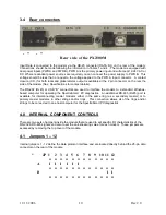
11/11/2006
11 Rev 2.0
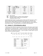
Jumper Driver
A
B
JP 1
RS-485 (diagnostic)
120 Ohm Rx
Hi – Z
JP 2
RS-485 (diagnostic)
120 Ohm Tx
Hi – Z
JP 3
RS–232
DCE
DTE
JP 4
RS–232
DCE
DTE
JP 5
RS-232
DCE
DTE
JP 6
RS-232
DCE
DTE
JP 7- JP10
Reserved
JP 11
RS-485
120 Ohm In
Hi – Z
JP 12
RS-422
120 Ohm In
Hi – Z
Hi – Z
- high impedance
DTE
- data terminal equipment (computer terminal handshaking)
DCE
- data communications equipment (modem handshaking)
*
- default factory setting of Jumpers
Input/Output termination resistors are usually necessary for RS-422 and RS-485 applications. Without
proper termination, the error rate of data transmission may be high due to an “echo” effect on the
electrical connection. With the addition of a termination resistor at the beginning or at the end of the
electrical bus, this “echo” effect is greatly reduced. The termination resistors are 120ohm resistors are
located inside the modem. Termination resistors are not required for RS-232 applications.
4.2 Jumpers 13 - 24 (Antistreaming values)
In order to prevent the network from ‘hanging-up’ in the event that one of the modems or ports continues
to transmit data on its own, the modems in the network can be set to terminate transmission after a
specified time-out (or Antistreaming time). Jumpers 13 through 24 are used to set the appropriate
timeout interval. This time can be set to 10ms, 0.1sec, 2sec, 30sec (see the table below for proper
jumper settings for the desired timeout interval. This set of jumpers is located under the top cover
directly in front of the front panel DIP switches.
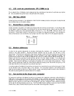
JP 13 14 15 16 17 18 19 20 21 22 23 24
o o o o o o o o o o o o
I I
o o o o o o o o o o o o
JP 13 - JP 22
- -
Reserved
JP 23
JP 24
ON
ON
Antistream
30 sec *
JP 23
JP 24
OFF
ON
2 sec
JP 23
JP 24
ON
OFF
0.1 sec
JP 23
JP 24
OFF
OFF
10ms
* -
factory setting of Jumpers 23 -24
Summary of Contents for 2300M Series
Page 6: ...PX 2300 SELF HEALING RING MULTIDROP FIBER OPTIC MODEM User s Manual...
Page 28: ...11 11 2006 23 Rev 2 0...
Page 44: ......

