11/11/2006
10 Rev 2.0
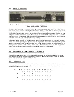
3.4 Rear connectors
- + - +
Rear side of the PX2300M
Input Data is connected to the modem via the DB-25 connector (DATA I/O) on the rear of the modem.
Connections should be made following the information in Tables 1 and 4 . The modem is equipped with
dual power inputs (PWR A and PWR B). PWR A is the primary power input and will accept 12-24V AC or
DC. Where redundant power sources are required you can connect the power supply to PWR B. This
voltage should be less than or equal to the voltage applied to the PWR A input connector. A contact
closure (C.C.) for both local and global alarms output is available at the 2 pin connector
on the rear the
side of the modem (See Specifications for contact details).
The RS-232 (RJ45) or USB “B” connectors are used to interface the modem to a standard Windows-
based computer for operating the SpectraSmart PC diagnostics. An additional RS-485 (RJ45) port is
available for interconnecting master modems either in the same ring (as a secondary master) or to
primary master modems in other strings and/or rings. This connection allows all of the rings and/or
strings to be connected to one host computer for the SpectraSmart PC diagnostics.
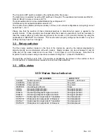
4.0 INTERNAL COMPONENT CONTROLS
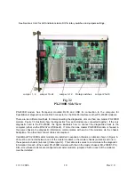
There are two sets of jumpers inside the module that are used to set specific I/O characteristics of the
RS-232 & RS-485 signals and also to set the anti-streaming value for each modem. These jumpers are
accessed by removing the top cover of the module.
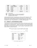
4.1 Jumpers 1 – 12
Internal jumpers 1 - 12 define the data protocol interface and are located directly behind the 25-pin data
connector on the rear of the module.
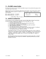
*
JP 1 2 3 4 5 6 7 8 9 10 11 12
o o o o o o o o o o o o
A I I I I I I
o o o o o o o o o o o o
B I I
o o o o o o o o o o o o
Summary of Contents for 2300M Series
Page 6: ...PX 2300 SELF HEALING RING MULTIDROP FIBER OPTIC MODEM User s Manual...
Page 28: ...11 11 2006 23 Rev 2 0...
Page 44: ......

