DMU380SA Series
User’s Manual
________________________________________________________________________
Doc# 7430-0026 Rev.01
Page 19
7.
Upon completion of the “Mag Alignment Procedure”, the heading accuracy
should be verified with all third party systems active using a known reference
such as a compass rose, GPS track or a calibrated compass. Heading
inaccuracies greater than the values specified on the data sheet or fluctuating
heading performance may be an indication of magnetic field disturbances
near the unit.
IMPORTANT
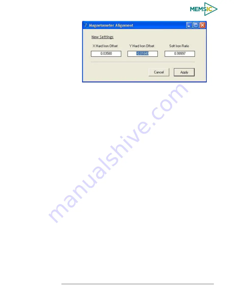
An acceptable calibration will provide X and Y Hard Iron Offset Values of < 2.5 and a
Soft Iron Ratio >0.95. If this procedure generates any values larger than stated above, the
system will assert the softwareError
dataError
magAlignOutOfBounds error flag. See
section 9 for details on error flag handling. Note that the current release of the software
does not have this functionality. Future releases of software will restore this
functionality. The magnetometer ranges is +/- 4 gauss, thus 2.5 gauss is the
recommended maximum hardiron that should be tolerated for the installation and still
provide ample resolution and headroom to properly determine the earth’s magnetic field
(strength < 0.5 gauss). If the hard iron estimates are larger than 2.5 gauss, then a
different installation location should be investigated.
Read Unit Configuration
3.13
NAV-VIEW allows users to view the current settings and calibration data for a given
DMU380SA Series
unit by accessing the “
Read
Configuration” selection from the
“Configuration” drop down menu
(See Figure 12). From this dialog, users can print a
copy of the unit
’
s current configuration and calibration values with the click of a button.
Simply select the “Read” button at the top of the dialog box and upon completion select
the “Print” or “Print Preview” buttons to print a copy to your local ne
twork printer. This
information can be helpful when storing hard copies of unit configuration, replicating the
original data sheet and for troubleshooting if you need to contact MEMSIC
’s Support
Staff.
Figure 12.
Read Configuration


