211 of 271
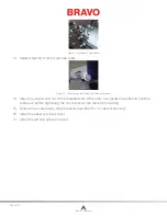
Figure 3 - X-Motor Harness Connections
11. Disconnect the x-harness hall and motor leads (marked “CONTROL PCB X MOTOR” and
“CONTROL PCB X HALL/ENC”) from the main PCB at locations J5 and J6.
12. Use wire cutters and cut any cable ties tieing the x-motor harness leads to any of the other har-
nesses and pull the x-motor harness through the cable access hole to the lower bed.
13. Cut any cable ties tieing the x-harness leads to the z-motor harnesses.
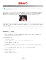
Figure 4 - X-Motor Mounting Screws
14. Remove the X-motor bracket mounting screws and remove the x-motor together with the bracket
from the machine.
15. Remove the x-motor bracket from the x-motor and install it on the replacement x-motor and tight-
en the screws to the torque specifications.
16. Reinstall the x-drive pulley to the x-motor so that the index arrow (marked on the pulley rim when
originally installed) is facing straight up and tighten the screw to 8 in-lbs[0.9 Nm] of torque using
a torque wrench.
17. Run the x-harness on top of the z-motor harness and along the same path as the z-harness down
to the main PCB and tie them together using cable ties about every 3-4 inches.
18. Connect the x-motor harness leads into the main PCB at locations J5 and J6.
19. Tension the x-cable using the procedures provided in X-drive cable installation.
20. Reinstall the left upper arm side cover and tighten the screws.
21. If you do not have any further work on the inside of the machine, install the covers in the reverse
that you removed them.
Table of Contents


