
Ethernet connector
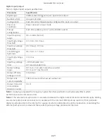
The WebDAQ has one 10 Base-T/100 Base-TX, auto-nego a on, high-speed communica on port. The port
connector is an RJ-45, eight-posi on connector. The Ethernet port accepts shielded or unshielded twisted pair
cable. The maximum communica on distance without using a repeater is 100 m (328 ).
Ground connector
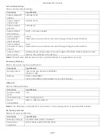
The WebDAQ ships with a ground screw in the connector labeled #6-32. To ground the WebDAQ chassis, a ach
a ring lug to a 14 AWG (1.6 mm) wire. Connect the ring lug to the grounding screw on the WebDAQ rear panel.
A ach the other end to a safety ground.
USB connectors
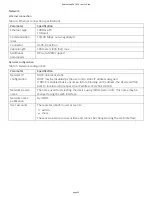
The two high-speed USB ports can be used for connec ons to a mass storage device and approved WiFi
adapter.
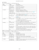
When removable media is plugged into the WebDAQ, the opera ng system opens it for wri ng. Use the FUNC
bu on or web interface to unmount the USB device before removing.
Use a self-powered hub when external media requires higher current
USB-powered hard drives may use an excessive amount of current during opera on. The WebDAQ
device could shut down or experience other errors if the power requirements of a connected device
exceed the power available. Use a self-powered hub if the current requirement of external media
exceeds 500 mA.
We recommend that you connect USB-powered hard drives before powering up the WebDAQ.
Acquiring data at high speeds can generate large file sizes
If you expect to acquire a large amount of data to a single file when logging to external media, do not
use media forma ed with the FAT32 file system. FAT32 is limited to a 4 GB maximum file size. If the log
file on FAT32 media grows beyond that size, a "File too large" error is returned and the acquisi on stops.
Before star ng a logging session of this type, reformat the media using a different file system such as
NTFS. Refer to the Frequently Asked Ques ons help topic for more informa on about file systems.
Analog input circuitry
Each channel passes through a differen al filter and then is mul plexed and sampled by a 24-bit ADC. The
channels share a common ground (COM) that is isolated from the digital subsystem.
The circuitry for one thermocouple channel is shown in here.
Figure 8. Input circuitry of one TC channel
RedLab WebDAQ 316 User's Guide
page 15






![Lambrecht power[cube] 30.95800.015000 Manual preview](http://thumbs.mh-extra.com/thumbs/lambrecht/power-cube-30-95800-015000/power-cube-30-95800-015000_manual_3388101-01.webp)


