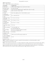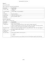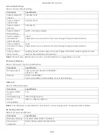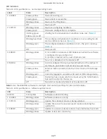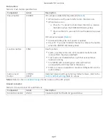
Open thermocouple detec on
Each channel has an open thermocouple detec on (OTD) circuit which consists of a current source between the
TC+ and TC– terminals. If an open thermocouple is connected to the channel, the current source forces a full-
scale nega ve voltage across the terminals.
Input Impedance
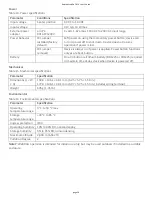
Each channel has a resistor that produces an input impedance between the TC and COM terminals. The gain
and offset errors resul ng from the source impedance of connected thermocouples are negligible for most
applica ons. Thermocouples with a longer lead length can introduce more significant errors.
Overvoltage protec on
WebDAQ provides 30 V overvoltage protec on between any two inputs.
Thermocouple measurement accuracy
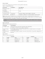
Thermocouple measurement errors depend partly on the type and accuracy of the thermocouple, the
temperature being measured, the resistance of the thermocouple wires, and the cold-junc on temperature.
For increased accuracy, follow the guidelines in the
sec on, and use the auto zero
channel to compensate for offset errors.
Cold-junc on accuracy
Heat dissipated by nearby heat sources can cause errors in thermocouple measurements by hea ng the RedLab
WebDAQ 316 terminals to a different temperature than the cold-junc on compensa on sensor. Thermal
gradient across the terminals can cause the terminals of different thermocouple channels to be at different
temperatures, which creates accuracy errors and affects the rela ve accuracy between channels.
The temperature measurement accuracy specifica ons include errors caused by the thermal gradient across
the RedLab WebDAQ 316 terminals for configura ons with the terminals facing forward or upward.
Auto zero channel
The RedLab WebDAQ 316 has an internal auto zero channel to compensate for offset errors. When enabled, the
WebDAQ measures the autozero channel and subtracts that measurement from the measurement of each
thermocouple channel. Use the web interface to enable auto zero. RedLab WebDAQ 316 specifica ons assume
that auto zero is enabled and applied to every sample.
Power-On Mode
WebDAQ Series hardware can be configured to start automa cally when power is applied, instead of requiring
users to press the POWER bu on. This is useful if the WebDAQ is opera ng in a remote loca on and a power
loss occurs. This "power-on mode" is enabled by removing a 2-pin jumper (labeled W1) from the WebDAQ
circuit board.
When jumper W1 is removed, the device does not shutdown completely unless the power adapter is
unplugged from the device or power source.
Perform the procedure below to remove jumper W1 from the WebDAQ circuit board and enable power-on
mode.
Cau on! The discharge of sta c electricity can damage some electronic components. Before removing
the WebDAQ device from its housing, ground yourself using a wrist strap or touch the computer chassis
or other grounded object to eliminate any stored sta c charge.
1. Power down the WebDAQ device and disconnect the power supply.
2. On the rear panel, remove the Ethernet cable, power cable, SD card, and any USB devices.
3. Remove the #6-32 ground screw.
RedLab WebDAQ 316 User's Guide
page 16


