background image

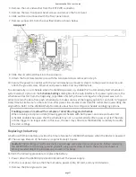
4. Remove the nut and washer from the EXT PWR connector.
5. Remove the two front panel bezel screws and remove the front bezel.
6. Slide out the circuit board with the front panel intact.
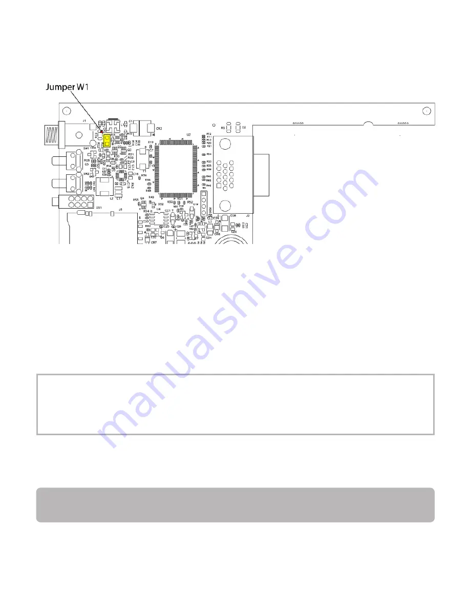
7. Remove jumper W1 from the specified loca on shown below.

8. Slide the circuit board back into the enclosure.
9. A ach the front bezel and secure with the two bezel screws removed in step 5.

10. Secure the power connector with the nut and washer (removed in step 4) to the power connector, and

a ach the ground screw, Ethernet and power cables, and any USB devices.

To automa cally run a schedule when the WebDAQ powers up, enable the "Automa cally start schedule on

system startup" op on on the Schedule Se ngs dialog box of the web interface. If a power cycle occurs, the

schedule will restart from the beginning, regardless of which job was running when the power was lost. In

order to retain the data from each schedule start, make sure to set the logging op on for each job to "Append

Date/Time to File Name" so that each run a er power loss creates a new data file rather than overwri ng the

original file. Refer to the WebDAQ help for details about how to configure schedule and logging op ons.

Enabling power-on mode with a complex or date/ me triggered schedule

When running a complex or date/ me-triggered schedule with both power-on mode and auto start

schedule enabled, be aware that the schedule may not run automa cally a er a power cycle if the date

or  me trigger is no longer valid. In this case, the user may s ll access the WebDAQ remotely to modify

the start se ngs.

Replacing the ba ery

A bu on cell lithium ba ery provides the  me reference for WebDAQ hardware when the device is powered

off. The average lifespan of the ba ery is approximately 10 years.

Cau on! The discharge of sta c electricity can damage some electronic components. Before removing

the WebDAQ from its housing, ground yourself using a wrist strap or touch the computer chassis or

other grounded object to eliminate any stored sta c charge.

Perform the following procedure to replace the ba ery.

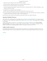
1. Power down the WebDAQ device and disconnect the power supply.
2. On the rear panel, remove the Ethernet cable, power cable, SD card, and any USB devices.
3. Remove the #6-32 ground screw.

RedLab WebDAQ 316 User's Guide

page 17

Summary of Contents for RedLab WebDAQ 316

Page 1: ...RedLab WebDAQ 316 User s Guide September 2019 Rev 5 Contents About this User s Guide Introducing the RedLab WebDAQ 316 Se ng up the WebDAQ Func onal Details Specifica ons ...

Page 2: ...to the RedLab WebDAQ 316 spring terminals A hazardous voltage is a voltage greater than 42 4 Vpk or 60 VDC to earth ground Ensure that hazardous voltage wiring is performed only by qualified personnel adhering to local electrical standards Do not mix hazardous voltage circuits and human accessible circuits on the same device Make sure that devices and circuits connected to the RedLab WebDAQ 316 are...

Page 3: ...ith a web browser such as a phone or tablet Remote monitoring and control Run simple to complex logging opera ons Flexible task scheduling Powered by Raspberry Pi The WebDAQ is designed with the Raspberry Pi Compute Module featuring a quad core processor with speeds up to 1 2 GHz 1GB RAM and 4 GB Flash memory Integrated opera ng system and web service The WebDAQ is a complete data acquisi on syste...

Page 4: ...unc ons are illustrated in the block diagram shown here Figure 1 Func onal block diagram Unpacking As with any electronic device you should take care while handling to avoid damage from sta c electricity Before removing the board from its packaging ground yourself using a wrist strap or by simply touching the computer chassis or other grounded object to eliminate any stored sta c charge Contents R...

Page 5: ... WebDAQ for wireless communica on Refer to the Configuring the WebDAQ for wireless communica on sec on for more informa on Connec ng directly to a PC Connect one end of the Ethernet cable to the connector on the WebDAQ rear panel and connect the other end directly to the Ethernet port on a PC The WebDAQ a empts to communicate with the host PC using 169 254 100 100 the link local address stored on t...

Page 6: ... web interface open a browser window and enter h p webdaq xxxxxx local where xxxxxx is the last 6 digits of the MAC address The MAC address is on a label at the bo om of the WebDAQ enclosure If your network is configured for the zeroconf protocol the WebDAQ web interface opens If the web interface does not open or an error is returned install a device discovery tool such as Bonjour Print Services R...

Page 7: ...wer bu on Configuring the network router for communica on across networks To communicate with the WebDAQ over the internet from a computer connected to a different network you must change the network configura on of the network router Cau on This procedure should only be performed by a network administrator or computer professional Incorrect se ngs can significantly disrupt a network In the following ...

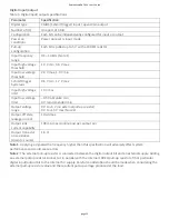
Page 8: ...s To restore network configura on and security se ngs to the factory default values use a paper clip to press the CONFIG RESET bu on When pressed the default network and security se ngs are wri en to the device and the WebDAQ is rebooted Factory default se ngs Parameter Specifica on IP address 192 168 0 101 subnet mask 255 255 255 0 Gateway 192 168 0 1 DHCP se ng DHCP link local enabled Security lev...

Page 9: ... or output alarm and features Schmi trigger inputs and open drain outputs All DIO channels are pulled high to 5 V Any digital bit can be configured with the web interface as a trigger to start or stop an acquisi on Any digital bit can also be configured to trigger an alarm and be driven high or low when an alarm occurs Spring terminal Connect up to 16 thermocouples TC0 TC0 to TC15 TC15 and two commo...

Page 10: ...s voltage within 1 2 V of all the connected thermocouples Minimizing thermal gradients Changes in the ambient air temperature near the thermocouple connectors or a thermocouple wire conduc ng heat directly to terminal junc ons can cause thermal gradients Observe the following guidelines to minimize thermal gradients and improve system accuracy Use small gauge thermocouple wire Smaller wire transfe...

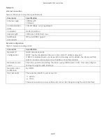
Page 11: ...et connector 2 Power bu on 5 SD card slot 8 Ground connector 3 Func on bu on 6 Factory reset bu on recessed 9 USB connectors 2 External power connector Connect the external AC adapter that shipped with the device to the connector labeled EXT PWR on the rear panel Click here to jump to the power specifica ons If using a different power supply than what was shipped with the hardware ensure that the su...

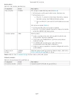
Page 12: ... to reboot the device release the bu on when the POWER LED blinks yellow Refer to Power On Mode for the procedure to remove jumper W1 and enable Power On mode The WebDAQ device can also be restarted or shut down using the web interface refer to the WebDAQ help for details Func on bu on The bu on labeled FUNC has two func ons it can be used to eject external media or to start stop an acquisi on Eje...

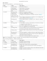
Page 13: ...led start condi on is met wai ng for job start condi on to be met Blinking green Data is being acquired job start condi on is met Off No error detected 3 ERROR Blinking yellow Error condi on is detected This LED blinks even when the so ware is configured to ignore the error Error state is cleared when the next schedule starts Off No error detected 4 MEDIA Blinking yellow A job is configured to log to ...

Page 14: ...en removable media is plugged into the WebDAQ the opera ng system opens it for wri ng Use the FUNC bu on or web interface to unmount the SD card before removing Acquiring data at high speeds can generate large file sizes If you expect to acquire a large amount of data to a single file when logging to external media do not use media forma ed with the FAT32 file system FAT32 is limited to a 4 GB maximu...

Page 15: ...WebDAQ device could shut down or experience other errors if the power requirements of a connected device exceed the power available Use a self powered hub if the current requirement of external media exceeds 500 mA We recommend that you connect USB powered hard drives before powering up the WebDAQ Acquiring data at high speeds can generate large file sizes If you expect to acquire a large amount of...

Page 16: ...la ve accuracy between channels The temperature measurement accuracy specifica ons include errors caused by the thermal gradient across the RedLab WebDAQ 316 terminals for configura ons with the terminals facing forward or upward Auto zero channel The RedLab WebDAQ 316 has an internal auto zero channel to compensate for offset errors When enabled the WebDAQ measures the autozero channel and subtracts...

Page 17: ...ata file rather than overwri ng the original file Refer to the WebDAQ help for details about how to configure schedule and logging op ons Enabling power on mode with a complex or date me triggered schedule When running a complex or date me triggered schedule with both power on mode and auto start schedule enabled be aware that the schedule may not run automa cally a er a power cycle if the date or me...

Page 18: ...ce window Device Info tab on the web interface Upda ng WebDAQ firmware Device firmware is bundled with the opera ng system web server and documenta on in a so ware update swu file Firmware updates are posted on the Meilhaus Electronic Firmware Updates page and are available for download Use the web interface to install the swu update file Open a browser window and enter h p webdaq xxxxxx local Help wh...

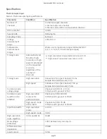
Page 19: ... resolu on requested scan rate is 1 Hz High speed requested scan rate is 1 Hz Timing mode High resolu on Conversion Time per channel 55 ms Sample Rate all channels 1 S s High speed Conversion Time per channel 740 µs Sample Rate all channels 75 S s Common mode voltage range Channel to COM 1 2 V min COM to earth ground 250 V Common mode rejec on ra o CMMR High resolu on mode at DC and 50 to 60 Hz Ch...

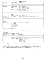
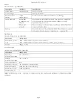
Page 20: ...sor can detect It is a func on of noise The values assume the full measurement range of the standard thermocouple sensor per ASTM E230 87 Table 2 Temperature accuracy specifica ons Parameter Condi on Specifica on Measurement sensi vity High resolu on mode Type J K T E N 0 02 C Type B R S 0 15 C High speed mode Type J K T E 0 25 C Type N 0 35 C Type B 1 2 C Type R S 2 8 C The following figures show th...

Page 21: ...Thermocouple Types J and N Errors Thermocouple Type K Errors RedLab WebDAQ 316 User s Guide page 21 ...

Page 22: ...Thermocouple Type T and E Errors Thermocouple Type B Errors Thermocouple Type R and S Errors RedLab WebDAQ 316 User s Guide page 22 ...

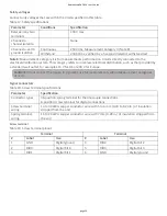
Page 23: ...in Output voltage range 0 V to 5 V no external pull up resistor 0 V to 15 V max Note 2 Output off state leakage current 10 µA max Output sink current capability 100 mA max con nuous per output pin Output transistor on resistance drain to source 1 6 Ω Note 1 Applying a signal with a frequency higher than this specifica on will adversely affect system performance and could cause errors Note 2 The exter...

Page 24: ...P link local sta c DHCP may be disabled by the user and a sta c IP address assigned If DHCP is enabled but is unsuccessful at obtaining an IP address the device will fall back to link local and request the IP address 169 254 100 100 Network device name The name used for detec ng the device using mDNS zero conf This name may be changed using the web interface Network name publica on By mDNS User ac...

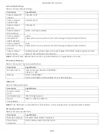
Page 25: ...l on the underside of the device Note 3 When factory defaults are restored any shared folders or mapped drives are reset Processor Memory Table 7 Processor memory specifica ons Parameter Specifica on Microprocessor Type Quad core Broadcom BCM2837 Speed 1 2 GHz Memory RAM 1 GB LPDDR2 Flash 4 GB eMMC 3 GB available for user data storage USB ports Table 8 USB specifica ons Parameter Specifica on Number o...

Page 26: ...EDIA Blinking yellow A job is configured to log to external media but the job hasn t started yet push bu on will not let you eject media Steady yellow External media is inserted into the SD card slot or USB storage port Blinking green Currently logging to an external SD card or USB storage device Steady green Media has been made safe for removal using the FUNC bu on but is s ll inserted in the devi...

Page 27: ...UNC Dual func on Ejects or safely unmounts all removable media for safe removal from the device default This func on is disabled when a job that uses external media is running The MEDIA LED is steady green when all media is unmounted but s ll inserted in the device Starts or stops an acquisi on requires configura on via the web interface Factory reset bu on CONFIG RESET Restores network se ngs to f...

Page 28: ...a ery BR1225 or CR1225 required to maintain me of day clock when device is powered off Mechanical Table 15 Mechanical specifica ons Parameter Specifica on Dimensions L W H 158 8 146 1 38 1 mm 6 25 5 75 1 50 in 177 0 146 1 38 1 mm 6 97 5 75 1 50 in includes spring terminal Weight 635 g 1 45 lb Environmental Table 16 Environmental specifica ons Parameter Specifica on Opera ng temperature range 0 C to 50 ...

Page 29: ...15 V for US or 230 V for Europe Cau on Do not connect the device to signals or use for measurements within Measurement Categories III or IV Signal connectors Table 18 Screw terminal specifica ons Parameter Specifica on Connector types 36 posi on spring terminal for thermocouple connec ons 6 posi on screw terminal for digital connec ons Screw terminal wiring 14 to 30 AWG copper conductor wire with 5 ...

Page 30: ...annel 5 HI 35 TC5 Channel 5 LO 8 TC6 Channel 6 HI 36 TC6 Channel 6 LO 9 TC7 Channel 7 HI 37 TC7 Channel 7 LO 10 TC8 Channel 8 HI 38 TC8 Channel 8 LO 11 TC9 Channel 9 HI 39 TC9 Channel 9 LO 12 TC10 Channel 10 HI 40 TC10 Channel 10 LO 13 TC11 Channel 11 HI 41 TC11 Channel 11 LO 14 TC12 Channel 12 HI 42 TC12 Channel 12 LO 15 TC13 Channel 13 HI 43 TC13 Channel 13 LO 16 TC14 Channel 14 HI 44 TC14 Chann...

Page 31: ...Meilhaus Electronic GmbH Am Sonnenlicht 2 82239 Alling Germany Phone 49 8141 5271 0 meilhaus de en RedLab WebDAQ 316 User s Guide page 31 ...

Reviews: