background image

Pinpointing Cable Faults in “Digiphone” Mode 


27 

4.2.1.2


Adjusting the Measurement Settings 

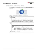
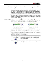
By pressing the knob, you can at any time switch from the 

measurement screen

 to the 

menu screen

 with the most important measurement settings: 


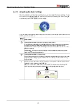
In this menu you can perform the following measurement settings: 

Menu 

item  Description 

BNR 

Activates/deactivates Background Noise Reduction (BNR). 
Background noise reduction is used to make it easier to detect acoustic pulses 

in environments with a lot of interference. Often it is not possible to distinguish 

background noise caused by rain or traffic, for example, from the actual signal 

and this makes acoustic pinpointing more difficult. 

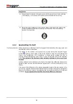
  Activates/deactivates the volume limiter. 

If this function is activated, the volume is limited to a maximum of 84 dB(A). 


When the volume limiter is being used, acoustic amplification should 

not be set too high! 
Excessive amplification, requiring the automatic limiter to constantly 

intervene, will attenuate the flashover noise. The background noise, on 

the other hand, would become more dominant as it is also amplified. 


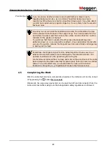
  Filter settings (see next page) 


Summary of Contents for digiPHONE+2

Page 1: ...1 digiPHONE 2 digiPHONE 2 NT digiPHONE 2 NTRX USER GUIDE Issue 01 01 2019 EN Article number 86599 ...

Page 2: ...2 ...
Page 3: ...ad Kent CT17 9EN T 44 1304 502100 F 44 1304 207342 E uksales megger com Dr Herbert Iann Str 6 D 96148 Baunach T 49 9544 68 0 F 49 9544 22 73 E team dach megger com Hagenuk KMT Kabelmesstechnik GmbH Megger USA Röderaue 41 D 01471 Radeburg Dresden T 49 35208 84 0 F 49 35208 84 249 E team dach megger com Valley Forge Corporate Centre 2621 Van Buren Avenue Norristown PA 19403 USA T 1 610 676 8500 F 1 ...

Page 4: ...r are hereby limited to a period of 12 months from the date of delivery Each component supplied by Megger within the context of warranty will also be covered by this warranty for the remaining period of time but for 90 days at least Each measure to remedy a claim under warranty shall exclusively be carried out by Megger or an authorized service station This warranty does not apply to any fault or ...

Page 5: ... General information on locating faults with the device 29 4 3 1 Interpreting the measured value and direction data 29 4 3 2 Volume Settings 31 4 3 3 Switching between automatic and manual trigger sensitivity setting 33 4 4 Procedure for fault detection 35 4 4 1 Tracing the Line 35 4 4 2 Approaching the Fault 36 4 4 3 Procedure 37 4 5 Completing the Work 39 5 Line and probe location in Ferrolux mo...

Page 6: ... the indicator unit 72 6 Pinpointing Sheath Faults in ESG Mode 73 6 1 Preparatory Measures 73 6 1 1 Tracing the Line 73 6 1 2 Starting Up the DC Impulse Generator 73 6 1 3 Connecting the Earth Spikes 74 6 1 4 Turning On the Indicator Unit 76 6 1 5 Adjusting the Settings 78 6 1 5 1 Adjusting the Basic Settings 79 6 1 5 2 Adjusting the Measurement Settings 80 6 2 Approaching the Fault 82 6 2 1 Gener...

Page 7: ... used to draw attention to potential hazards which have to be avoided by reading the manual Serves to highlight warnings and safety instructions that explicitly indicate the risk of an electric shock Serves to highlight important information and useful tips on the operation of the device system Failure to observe may lead to unusable measurement results It is important to observe the generally app...

Page 8: ...000 4 2 EN 61000 4 3 EN 61000 4 4 EN 61000 4 8 EN 61010 1 EN 50249 GPSG This product contains protected software which is licensed under the General Public License GPL and the Lesser General Public License LGPL This certifies your right to request the source code for these software components You can find detailed information on the GPL LGPL licenses under www gnu org Images from the Icons8 librar...

Page 9: ...ng a current of 100 Hz 120 Hz current for protection from corrosion can be located and traced For lines carrying an active signal generated by an audio frequency generator not only the path but also the laying depth the current strength and the direction of signal flow in case of a SignalSelect encoded signal can be determined Earth spikes for accurate pinpointing of sheath faults on plastic insul...

Page 10: ...oustic qualities for quick and reliable fault location High level of accuracy due to selective recording of magnetic fields Very stable sensor Trigger thresholds for acoustic and magnetic channels set fully automatically Possibility to switch to manual trigger threshold adjustment Patented extraneous noise reduction Automatic proximity mute Volume limiter which can be switched on and off Height ad...

Page 11: ...arth spikes 128309680 Connection cable red 2 m 128309356 Connection cable black 2 m 128309357 Contact sponge 128308944 Ferrolux receiver and accessories iFS receiver 1010472 Receiver cable 90025743 Headphones Wired headphones 90026322 Bluetooth headphones 90033686 Bags Bag Digiphone 1013130 Bag 3in1 1013131 Other accessories 6 x AA batteries type IEC R6 alkaline manganese 892334291 Manual 86599 Ch...

Page 12: ...accessories can also be ordered from Megger sales Accessory Description Item number Identification antenna IFA Mini antenna for cable identification 1011682 Wired headphones 90026322 Bluetooth headphones 90033686 GPS receiver set Consisting of the Holux GPS receiver M 1200 and a fitting carabiner with a lanyard 1013171 Accumulator pack Rechargeable battery pack with 2 Li ion batteries 9V 650 mAh s...

Page 13: ...cordance with IEC 60529 DIN VDE 0470 1 IP 54 The DPP SU sensor is defined by the following parameters Parameter Value Acoustic amplification 120 dB facility for limiting amplification to 84 dB A can be switched on and off Dynamic range Acoustic channel Magnetic channel 110 dB 110 dB Acoustic frequency range 100 to 1500 Hz Acoustic filters Software activated filters for improving acoustic perceptio...

Page 14: ...quencies of 15 23 kHz Range 0 1 7 m line location 0 1 15 m probe location Accuracy 5 up to 2 m depth line or 5 m depth probe resp Manual depth measurement According to the 45 method Current strength measurement Accuracy Only with active frequencies 10 SignalSelect current direction indication Possible at all active frequencies if supported by the transmitter Weight incl telescopic handle 1 0 kg Di...

Page 15: ...tive 480 Hz 491 Hz 512 Hz 640 Hz 982 Hz 1090 Hz 1450 Hz 8440 Hz 9800 Hz 9820 Hz 32768 Hz Sensitivity 50 Hz 15 mA 491 Hz 1 5 mA 982 Hz 500 µA 8440 Hz 50 µA 32768 Hz 12 µA Dynamic range 120 dB Weight 180 g Dimensions without connection lead 54 mm x 75 mm x 22 mm W x H x D IP protection class in accordance with IEC 60529 DIN VDE 0470 1 IP 54 Identification antenna IFA optional ...

Page 16: ...s on the indicator unit Element Description Display Knob Function key 2 Earth spike connection sockets Sensor socket receiver connection Function key 1 Indicator unit on off when pressed and held Backlighting on off when pressed briefly LED indicates the device is switched on green and low batteries red Connection socket for headphones ...

Page 17: ...and the appropriate software mode started immediately The device is ready for operation after just a few seconds If the connected measurement accessory is not detected a selection screen appears with the available software modes Once proper connection of the measurement accessory has been checked the appropriate software mode can be selected manually The displayed selection depends on the software...

Page 18: ...witched back on at any time by briefly pressing the button again With the exception of a few functions the indicator unit is operated exclusively using the knob The functions available vary according to the respective current view Action Function in the measurement screen Function in the menu screen Opens the menu screen Opens the currently selected menu item Adaptation of the measurement range an...

Page 19: ...such high voltages is used certain safety regulations must be complied with It is essential to read the surge wave generator s manual before Connect the generator to the faulty wire and start applying surges with a surge voltage that will cause a flashover at the fault but which is also permitted for the cable type For more details about starting up the surge wave generator please read the accompa...

Page 20: ...d solid ground Because their acoustic qualities are different it is for the operator to decide which probe they prefer to use on such ground An advantage of the 3 point foot is that a sensor rod can be fitted on its underside This means that the foot does not need to be constantly unscrewed when the ground changes Fitting a suitable probe on the sensor 3 point foot preferred for uneven solid groun...

Page 21: ... in Digiphone Mode 21 This is how to attach the telescopic bar to the sensor This is how to adjust the height of the telescopic handle Attaching the telescopic handle to the sensor Adjusting the height of the telescopic handle ...

Page 22: ...nment One end of the cable is connected to the socket on the indicator unit and the other end to the socket on the top of the sensor see illustration The plug is aligned by the guides on the plug and the grooves on the socket You must hear and feel the plug engage Depending on the headphones used this is connected to the indicator unit via either a 3 5 mm jack socket or Bluetooth see page 87 Venti...

Page 23: ...ting see page 27 Filter setting for short fault distances Filter setting for medium fault distances Filter setting for large fault distances Bluetooth status messages see page 87 Scanning for visible devices Connecting to device Headset is connected GPS receiver connected Layout of the measurement screen Active functions and modes Battery status Active functions and modes see below Volume amplific...

Page 24: ...at any time and change any settings in two steps at most Each menu screen is made up as follows Menu structure Layout of the menu screens measurement screen menu screen Currently selected menu item Description of the currently selected menu item Active function Non active function Current menu level Return to the measurement screen Setup ...

Page 25: ... the operator touches the sensor s telescopic handle with their hand This protects the operator from excessively loud background noise which often occurs when the sensor is moved Alternatively muting or unmuting can also be activated manually at any time using the button see page 31 Activates deactivates the fault arrow When the fault direction indicator is activated an additional direction arrow ...

Page 26: ... function key F1 By pressing the function key the manual setting of the trigger sensitivity for acoustic pulses can be activated deactivated Since the acoustic triggering indicator is located on the right side of the display this function can only be assigned to function key F2 Sets the display language Sets the measuring unit The time difference between the arrival of the magnetic pulse and the f...

Page 27: ... in environments with a lot of interference Often it is not possible to distinguish background noise caused by rain or traffic for example from the actual signal and this makes acoustic pinpointing more difficult Activates deactivates the volume limiter If this function is activated the volume is limited to a maximum of 84 dB A When the volume limiter is being used acoustic amplification should no...

Page 28: ...ing the knob when in the measurement screen and switching to the menu screen Setting Description Filter off This filter setting provides the maximum bandwidth so that the flashover noise can be heard with as little distortion as possible However high level low frequency interference often occurs which makes time measurement more difficult when filtering is disabled Filter setting for short fault d...

Page 29: ...ous measurement If due to constant fluctuations the measurement values are shown only in grey for a longer dwell time it is recommended to carefully listen to the audio signal Also if no periodic acoustic signal can be made out here it is highly probably that the distance to the fault location is simply too great A change of position is recognised automatically by the sensor and should if possible...

Page 30: ...be measured no information The most recently taken measurement deviates by more than 10 from the previous measurement and is not considered for a direction indication closer to the fault The last change in position decreased the distance to the fault further from the fault The last change in position increased the distance to the fault in close proximity to the fault The last two readings indicate...

Page 31: ...e two function keys is used as mute button the headphones can be muted at any time by pressing this key Muting is switched off by pressing the key again or increasing the volume Furthermore the menu item in the device settings can be used to activate the Automatic Proximity Mute APM feature see page 25 When enabled muting occurs as soon as your hand touches the telescopic handle In this mode manua...

Page 32: ...ion with the sensor receiving pulses the less audible the interference becomes Each time the sensor is moved the information gained about the background noise is discarded After each position change the level analysis starts afresh when the first surge pulse arrives The current status is indicated by a symbol on the top of the display assuming background noise reduction is enabled in the device se...

Page 33: ...c trigger or for the acoustic trigger it is possible to switch from an automatic to a manual sensitivity setting at any time in measuring mode A circular actual value display now appears around the respective trigger symbol which symbolises the currently set trigger sensitivity Manual trigger sensitivity setting for electromagnetic pulses active Manual trigger sensitivity setting for acoustic puls...

Page 34: ...his also happens if both manual sensitivity settings are activated In this case the trigger sensitivity level that was activated first is locked while the other sensitivity level can be adjusted manually To adjust a sensitivity setting that is locked briefly press the relevant function key again To return to the automatic trigger sensitivity setting press and hold the relevant function key for at ...

Page 35: ...re Please proceed as follows Step Action 1 Place the sensor on the ground with the arrow pointing in the direction where you believe the cable to be running 2 Wait until the indicator unit signals the arrival of the magnetic pulse 3 If the green cable compass is not displayed at all or jumps back and forth sporadically the signal strength is not yet sufficiently high to reliably measure the positi...

Page 36: ...p which helps to discern the flashover noise from the background noise in the headphones The coincidence of these events enables the user to correctly identify the flashover noise when it occurs at the same time as the magnetic pulse The volume of the flashover noise normally continues to rise as you near the fault Another indicator for the distance to the fault is the transit time difference betw...

Page 37: ...npointing Cable Faults in Digiphone Mode 37 4 4 3 Procedure The following is an example of how the indicators transit time direction indicator change as the operator nears and goes past the fault Diagram ...

Page 38: ...d try to continue the search in the other direction from the starting position 3 Remain in this position for a few pulses to allow the background noise reduction see page 37 to improve the accuracy of the measurements and the acoustics 4 Continue along the cable route one step at a time correcting the alignment if necessary and stay for a few pulses in each position As you near the fault the trans...

Page 39: ...considerably directly after you pass the position Instead the magnetic level remains virtually unchanged up to and beyond the fault Sometimes the magnetic signal from the actual target line crosses over to an adjacent line and this adjacent line is displayed by the direction indicator The operator could then even end up following the wrong line We therefore recommend that you trace and mark out th...

Page 40: ...on see page 70 Receiver iFS for line location and tracing see page 51 The acoustic signal is emitted during the current positioning in Ferrolux mode via the Pizo loudspeaker integrated into the indicator unit unit Use of the headphones is therefore not absolutely necessary in principle but is recommended especially if the measurement is performed in a particularly noisy environment Depending on th...

Page 41: ...imum method Maximum method Super maximum method Active frequency selected see page 45 Probe locating mode active see page 64 Bluetooth status messages see page 87 Scanning for visible devices Connecting to device Headset is connected GPS receiver connected Layout of the measurement screen Active functions and modes Battery status Active functions and modes see below Currently set frequency Signal ...

Page 42: ... enter any setting with a maximum of two operating steps By principle the individual menu screens have the following layout Menu layout Elements of the menu screens Measurement screen Menu screens Currently selected menu item Back to measurement screen Activated function Current menu level Measurement series Description of the currently selected menu item ...

Page 43: ... the display unit to be connected to a Bluetooth enabled headset or GPS receiver see page 87 When connected to a GPS receiver the GPS coordinates transmitted by the GPS receiver are permanently displayed on the measurement screen Furthermore the coordinates are written to the internal memory together with the respective measurement values whenever a new measurement point is saved During the locati...

Page 44: ...r Only the frequencies which have been activated in the basic settings are taken into consideration see previous page After pressing the function key the volume can be adjusted using the selector knob The mute button can be activated deactivated by pressing the function key By pressing the function points the current measured data and GPS coordinates only with an existing connection to a Bluetooth...

Page 45: ...aracteristic than a metal conductor Adjusting the speaker or headphone volume In parallel to the bar chart display the signals recorded by the antennas are also continuously reproduced acoustically via the speakers or the connected headphones in order to give the user an indication of the changes to the signal strength even when he is not looking at the display The frequencies which are audible to...

Page 46: ...982 Hz 1090 Hz 1450 Hz 8440 Hz 9800 Hz 9820 Hz 32768 Hz Typical transmission frequencies These frequencies are supported by the majority of the transmitters in the Ferrolux series and can also be fed in by these as a SignalSelect modulated signal 512 Hz 640 Hz Typical probe frequencies To change the currently set frequency the menu screen must be called up by pressing the knob and the menu item se...

Page 47: ...oached the signal level increases slowly and continuously The maximum signal is found directly above the line Minimum method During line tracing with the minimum method only the signal received by the vertically arranged antenna is evaluated The signal display and the pitch are initially greater when a line is approached A considerable drop in the signal strength must be recorded in close proximit...

Page 48: ... place so that the levels always remain comparable to the previous maximum level However the user can adjust the sensitivity using the knob at any time while he is in the measurement screen In this way the sensitivity can at least be increased again manually if the signal level drops significantly during the course of location tracing for some reason or other and only extremely weak deflections ta...

Page 49: ...urrent measurement series as a new measurement point As a result the diagram with the measurement values recorded up to this point is displayed for about 3 seconds before the indicator unit automatically switches back to the measurement screen The saving of a measurement point is only possible if the receiver is directly above the line Otherwise the function key is inactive Saving of measurement p...

Page 50: ... a new measurement series started as soon as the next measurement point is saved Using this menu item the currently recorded measurement series can be reset without the values being placed permanently into the internal memory A new measurement series is started as soon as the next measurement point is saved Using this menu the saved measurement series can be selected and displayed again All record...

Page 51: ...nment with reference to the line or probe to be located the receiver must be carried laterally in front of or next to the body and the side marked must be facing the front The indicator unit must be worn on the body so that the connections are located at the side furthest away from the body To ensure that the user has the most ergonomic posture possible the handle of the receiver can be rotated ar...

Page 52: ...The transmitter and receiver are synchronised with each other in this way and a possible phase shift is compensated for The use of this test also ensures that the connection lines have not been unintentionally connected the wrong way round If no SignalSelect coded signal is coupled in by the transmitter that is used the reset does not need to be carried out of course Proceed as follows to carry ou...

Page 53: ...ty of the SignalSelect detection see page 57 should be either very high or maximum and the should be indicating the correct signal flow direction 5 If the circle around the SignalSelect display is not completely filled in green call up the menu item in the menu to carry out a SignalSelect reset and synchronise the receiver with the transmitter signal in an optimum way ...

Page 54: ... significant level deflection The maximum method is particularly suitable for this general locating of the line since this also provides a signal response at quite a distance from the line However with very deep lines the super maximum method may be the better option A good indication of the fact that a sufficiently strong signal level is being received from the line being searched for is the gree...

Page 55: ...e black arrows on the left and right next to the receiver icon The following applies the more the arrow is filled in the further away the line is The filling of the arrow should decrease while approaching in the indicated direction the signal level should increase and the green line should move further toward the centre At the point of the absolute signal maximum with minimum method signal minimum...

Page 56: ...ntly lower on these lines the signal level received at the surface could adopt similar values in unfavourable cases if the line on which the signal is being transmitted is laid significantly deeper than the adjacent lines for example Please read the associated operating manual for information about how SignalSelect mode is activated at the transmitter A prerequisite for correct evaluation of the S...

Page 57: ...r the phase shift internally another SignalSelect reset should be carried out provided that the line and the current flow direction can still be clearly determined The procedure is the same as the one for carrying out an initial reset at the connection point see page 52 However another adjustment should normally only be necessary a few kilometres away from the fault location The quality fill level...

Page 58: ...ame mains frequency is greater with passive frequencies NOTE Risk of damage to buried lines The measured depth value should not be regarded as assured since a range of outside influences can affect the accuracy of the depth measurement Proceed with appropriate caution during excavation work The prerequisite for the most accurate depth measurement possible is that the receiver should be in as exact...

Page 59: ...s means that if the receiver is offset to the side at an angle of 45 to the path of the line the lateral distance to the line corresponds to the depth of the line Proceed as follows to check this for the current target line Step Action 1 Select the maximum method in the measurement settings see page 45 The 45 method only works in this mode as described 2 Hold the receiver exactly above the line in...

Page 60: ... result has not been influenced by adjacent lines or only slightly influenced The situation is different if the transmitter signal is coupled into an adjacent line or a second supply line with the same mains frequency is running directly parallel to the line A significantly less homogeneous field therefore forms around the lines which leads to a significant difference between the measured distance...

Page 61: ...suitable transmitter should be placed directly above the line to be traced and a high frequency signal e g 9 8 kHz or 33 kHz coupled in inductively If only part of the line needs to be traced e g for terrain examination as preparation for excavation work the first step is to find the line in the affected area and determine its alignment If a direct connection to the line is not possible inductive ...

Page 62: ... coupled with a GPS receiver see page 43 the GPS coordinates of the individual measurement points are also stored A map display of the path of the line can be created in the office later using this data Branches in the path of the line can be recognised from the fact that the current is divided between both lines The ratio depends on the length of the respective branches and the earthing condition...

Page 63: ...examination It is automatically reduced as soon as a signal response is detected Each detected line should be routed and marked in both directions as far as the location at which it leaves the area that is being examined Terrain examination should then continue The following notes must be taken into consideration during terrain examination Examination must take place in maximum mode When a transmi...

Page 64: ...elves and passive probes which are connected to an appropriate transmitter via a cable Depending on the field of application the probes also differ in design transmission power and frequency For example camera probes typically transmit at a low frequency 512 Hz 640 Hz so that the signal can extend even beyond metallic lines If the receiver is positioned directly above the probe and the two are ali...

Page 65: ... The symbol indicates that probe location mode is activated A compass needle appears in the centre of the display which if the receiver is correctly aligned indicates the direction of the probe 2 Select the frequency of the probe or the transmitter to which the probe is connected see page 45 The locating mode cannot be changed Probe location is always conducted in maximum mode 3 If possible push t...

Page 66: ...the probe the signal level will decrease again 5 Determine the position at which you receive the maximum signal strength and verify this by moving the receiver approximately half a metre to the left right front and rear If the purpose of locating the probe is to trace a line it is advisable to mark the position or save it as a measuring point see page 49 Saving the position as a measuring point an...

Page 67: ...ed that you work in either super maximum or minimum mode In addition the section of the line in which the fault or sleeve is suspected to be located should be traced as accurately as possible before the actual location procedure During the actual fault sleeve location procedure this section must then be retraced Whilst doing so measuring points at suitable intervals must be saved and marked direct...

Page 68: ...m mode However since the minimum mode is more susceptible to overlapping from single core cables routed parallel to the multicore cable it is preferable to carry out the measurement using maximum mode The relevant cable section should be traced and marked before the actual fault or sleeve location procedure takes place as this will allow the route to be retraced more quickly at a later stage In th...

Page 69: ...faulty wires and a typical longitudinal twist can be measured Since sleeves represent an interruption to the consistent longitudinal twist the Twisted Field method may be particularly useful for locating longer sleeves To perform the location procedure trace the section of cable in which the sleeve is suspected to be located and watch for a short but significant deviation from the usual level rhyt...

Page 70: ...41 in that the elements relevant for finding the line direction arrows line orientation are not displayed The strength of current and the depth are also not displayed when measuring using the reader coil The reader coil is applied directly on the cable for the purposes of measurement with the curved base of the reader coil in contact with the cable To ensure that the SignalSelect display see page ...

Page 71: ...ected consumers do not have to be isolated Ensure that the transmitter clamp is placed around the shield and the inner conductors of the cable to be read out This cable can then be reliably identified using the SignalSelect display during the actual reading process as either a return signal or no signal at all will be measured from all other cables If it is not possible to couple the signals using...

Page 72: ...io frequency signal must be applied to a short circuited pair of wires A consistent change in signal level will be measured from the inductively coupled cable whereas the signal response from the neighbouring lines will remain relatively constant 5 7 Switching off the indicator unit After successful location of the cable or fault the indicator unit can be switched off with a long press of the butt...

Page 73: ...d When equipment creating such high voltages is used certain safety regulations must be complied with It is essential to read the manual for the DC impulse generator For a DC impulse generator any equipment and system can be used which can be prepared for pulsed DC voltage to locate sheath faults This particularly includes equipment from the MFM series but also various other testing and fault loca...

Page 74: ...t the earth spikes to the indicator unit CAUTION Hold the earth spikes by the insulated handles only In the immediate vicinity of the potential gradient dangerous voltages may occur at the surface The displayed voltage values are not suitable to draw a conclusion about the actual risk When connecting the earth spikes observe the designated colours of the connection cable and connection socket ...

Page 75: ...tions in which it was only possible to pre locate the fault position very vaguely or even where it was not possible at all you will have to approach the position from a greater distance However to be able to measure the smaller step voltage the earth spikes need to be placed at larger intervals from one another see page 83 For this purpose customised connection cables of 15 metres in length are av...

Page 76: ...nt screen displays all the relevant information which could be useful when approaching the sheath fault The symbols at the top right of the measurement screen indicate the following functions and measurement modes Symbol Description High pass filtering is active see page 80 Smoothing filter is active see page 80 Automatic zoom is active see page 80 Turning on Layout of the measurement screen Activ...

Page 77: ...dition to the standard view the device offers an alternative view for showing the time progress of the step voltage over 16 seconds This alternative display can be activated or deactivated at any time via the menu item see page 80 Alternative view ...

Page 78: ...any time and change any settings in two steps at most Each menu screen is made up as follows Menu structure Layout of the menu screens Measurement screen Menu screen Currently selected menu item Description of the currently selected menu item Non active function Active function Current menu level Return to the measurement screen Setup ...

Page 79: ...g this menu item the following functions can be assigned to the two function keys of the indicator unit Each press of the function key switches between the two measurement screens The high pass filtering see next section can be activated deactivated by pressing the function key The smoothing filter see next section can be activated deactivated by pressing the function key The automatic zoom see ne...

Page 80: ... by turning the knob The currently set zoom level is permanently displayed in a small bar below the bar graph or diagram see page 76 Activating deactivating the high pass filtering Select this function if severe interference affects the measurements such as in the vicinity of tram installations The high pass filter suppresses any constant components whereby only the edges are displayed but not the...

Page 81: ...n this way low interference signals are ignored by the system and unnecessary adjustments of scaling are avoided If it becomes necessary to begin fault location at a greater distance from the sheath fault the useful signal in certain circumstances is barely above noise level In these situations the maximum sensitivity should be activated and the measurement range be expanded downwards to 5 μV ...

Page 82: ... spikes and approaching the deflection direction following the fault position The sheath fault is located in the direction of the earth spike which is connected with the black measuring lead The sheath fault is located in the direction of the earth spike which is connected with the red measuring lead To ensure a reliable indication of the direction note the following guidelines for basic handling ...

Page 83: ...with a longer one This would require a second person to speed up the work The ground conditions have a huge effect on the electrical coupling and the precision of the system Changing coupling behaviour while pinpointing can for instance cause the measured voltage to drop even when approaching the fault position Dry asphalt ground acts as an insulator and does not provide sufficient earth contact f...

Page 84: ...olarity also indicates the direction of the fault position at this point At half way point between the generator and the fault position the signal strength reaches a minimum position On moving nearer to the fault position the signal strength increases again The maximum signal strength is measured when one of the earth spikes is directly above the fault If the fault is exactly between the two earth...

Page 85: ... 80 Switching to the alternative view which shows the voltage curve over the last 16 seconds see page 80 could make identifying the periodical DC voltage impulses easier 3 Follow the cable route in the direction of the signal without changing your orientation Take some more measurements every few metres When approaching the fault position the distance between the earth spikes can be gradually decr...

Page 86: ...f the signal level indicates towards the black earth spike at each control measurement the fault position has been successfully verified 7 Repair the damaged section and test the sheath again for any further damage 6 3 Completing the Work After the sheath fault has been successfully pinpointed the indicator unit can be turned off by pressing the button for 3 seconds Afterwards the DC impulse gener...

Page 87: ...S receiver the current GPS coordinates can be shown in the display during the current measurement In Ferrolux mode the GPS coordinates are also stored in the measurement series so that the line route can be tracked later on the PC A suitable model can be ordered as an accessory see page 12 Only one Bluetooth connection can be established at any one time It is therefore not possible to pair headpho...

Page 88: ...arch for available Geräten Result The indicator unit returns to the measurement screen and searches for visible Bluetooth devices for about 30 seconds The current search is indicated by the flashing symbol When the search is complete the list of devices found is displayed 4 Use the rotary knob to find the correct device based on the identifier and press the rotary knob to pair Result After success...

Page 89: ...e menu item to call up the list of known devices Result The list of known devices is displayed If one of the devices is currently connected to the display unit it is highlighted in green 4 Use the rotary knob to find the correct device based on the identifier and press the rotary knob to establish a connection Result The display unit switches to the measurement screen and attempts to connect to th...

Page 90: ...e the software your system must fulfil the following requirements Operating system 64 Bit Windows 7 or later Processor Intel i5 or higher RAM min 4 GB Interfaces USB 2 0 Proceed as follows to establish a connection between the indicator unit the sensor and the software Step Action 1 Connect the indicator unit or sensor to the PC via the USB cable 2 Switch on the indicator unit not necessary with a...

Page 91: ...easurement series hold down the Ctrl key Or you can mark all the measurement series displayed with a single click using the button above the measurement series list 3 Click on to export the marked measurement series 4 Save the file in the required folder and under the required name 5 The exported measurement series can be imported in a suitable application for displaying KML files and displayed th...

Page 92: ... possible 3 Confirm the confirmation prompt 8 2 Updating the firmware Proceed as follows to update the firmware of the indicator unit or a sensor Step Action 1 Click on the icon in menu bar on the left 2 Click on and select the relevant firmware file Result The software automatically checks whether the firmware file is appropriate for the connected hardware and only enables the button for starting...

Page 93: ... which provides adequate protection against mechanical damage and dirt The storage temperatures shown in the technical data must be adhered to Only use the carry bag supplied to transport the device Please note that the ambient conditions along the entire transport route must comply with the technical data During transport never hold the device by the connection cables only Long periods out of use...

Page 94: ... which will lead to a worsening of the support for the sensor If this is the case you can either send the telescopic handle to an authorised service centre or you could order a quarter turn lock as a replacement part article number 128309580 and carry out the replacement yourself If you choose to carry out the repair independently you must first loosen the union nut at the lower end of the handle ...

Page 95: ...to simbolo indica che il prodotto non deve essere smaltito come un normale rifiuto domestico In quanto prodotto B2B può anche non essere smaltito in centri di smaltimento cittadino Se si desidera smaltire il prodotto consegnarlo a un organismo specializzato in smaltimento di apparecchiature elettriche vecchie Šī zīme norāda ka iztrādājumu uz kura tā atrodas nedrīkst izmest kopā ar parastiem mājsai...

Reviews: