background image

Running MegaVision as a plug-in application for different NMS
platforms

There some differences between the way MegaVision-WEB and MegaVision Classic work
under standard NMS Platforms. MegaVision-WEB uses its Java-based WEB interface to
access its GUI from different platforms. Please, note that in order to achieve such integration
there should be a PC running MegaVision-WEB server plugged somewhere in the network,
which runs 24x7 collecting management data.
MegaVision Classic uses native MS-Windows GUI, however the list of supported NMS
platforms is limited to:

1)


HP OpenView Windows (version 7.1 and higher, including HP OV Professional
Suite).

2)


Castle Rock SNMPc 4.x or SNMPc NT 5.x.

3)


Cabletron SPECTRUM 4.0 rev1 and higher (WinNT 3.51).

4)


HP OV NNM (WinNT, Win2000).

It is recommended using MegaVision Classic for the above PC NMS platforms. If you need to
manage MegaVision supported devices under UNIX based platforms, use MegaVision-WEB.

MegaVision-WEB under HP OV NNM UNIX

MegaVision-WEB GUI can be accessed from any standard NMS platform. Please, review the
following notes for HP OV NNM UNIX as an example how to organize such interface.
HP OV NNM Versions 5.x and higher allow to call WEB browser for any device icon, which is
located on the HP OV NNM Map.  This feature may be used to provide seamless GUI access
to all managed devices.

Here are the steps you should perform.

1.


Use HP OV NNM "Edit"/"Find"/"Object by Attribute"/"IP Address" to find the PC
which is running MegaVision-WEB (IP address" "a.b.c.d"). (Note: If you cannot find
such icon, you must create it manually via "Edit"/"Add Object").

2.


Use "Right Mouse Button click"/"Object Properties" to open HP OV NNM "Object
Properties" Window. Select "General Attributes" and make sure that
"isHTTPsupported" and "isHTTPmanaged" properties are enabled. Enter the
"ManagementURL" like this:  b1. If you did not reconfigure the HTTP port value (it is
80 by default) enter: "http://a.b.c.d/”; b2. If you reconfigured the HTTP port value (e.g.
port=2000) enter: "http://a.b.c.d:2000/"

3.


Use "Tools"/"WEB browser"/"Management Page" in order to get GUI access to all
supported devices. You may leave the browser window open and switch to it
whenever you need it. Please note that polling is done automatically and you will
always see the most recent status in this window.

4.


Optional. You may perform step b. for any supported device located on the HP OV
map. In this case you can receive MegaVision-WEB GUI without looking for the
MegaVision-WEB PC Icon first.

Summary of Contents for Network Management System

Page 1: ...MegaVision Network Management System User Manual MRV Communications Inc URL http www mrv com...

Page 2: ...er The seller reserves the right to revise this publication without obligation to provide notification of such revisions While reasonable precautions have been taken the seller assumes no responsibili...

Page 3: ...ndows 9 Graphics support 10 Alarms 11 SNMP MIB Browser 12 Interfaces monitoring 13 RMON support 14 Adding and deleting devices Describe window 15 Autodiscovery 16 Links 17 Generic SNMP and TCPIP devic...

Page 4: ...ss http IP Address where IP Address is IP Address of the PC MegaVision WEB is running on This feature allows to monitor configure your network from any point in the world which has Internet Intranet c...

Page 5: ...rough use of passwords Two levels of passwords allow monitoring and display only user or monitoring display and configuration of the devices supervisor MegaVision WEB additionally contains the followi...

Page 6: ...evice icon The Device Main window appears It usually represents the device front panel with real time status LEDs Ports that are grayed out are inactive Click on the Company device logo symbol to ente...

Page 7: ...d sites http a b c d where a b c d is the IP address of the computer running MegaVision WEB Do not forget to uncheck the check box Require server verification https for all sites in this zone Otherwis...

Page 8: ...ES which belong to remote network computers The issue is connected to selecting MegaVision WEB root directory This may crash MegaVision WEB server b It is strongly recommended NOT TO USE long director...

Page 9: ...m Configuration Pentium PC 450 MHz 19 Monitor 64 MB Memory 128 MB recommended 40 MB available hard disk space OS Win95 Win98 WinNT Win2000 WinNT recommended 2 Client Platform Minimum Configuration CPU...

Page 10: ...soles However there is no automatic limitation for this configuration Login modes are selected in the Login window when you load the application To Login as a Supervisor The following directions descr...

Page 11: ...ow to login for the first time you enter MegaVision as USER After this initial login procedure you can set up a new password for USER mode or set up the Password window to bypass the Login window At t...

Page 12: ...correct Old password Note If you are logging in as a supervisor for the first time press Tab in the Old Password field If you are logging in as a user enter the default password default is USER 3 Ente...

Page 13: ...phical depiction of the device s front panel See About the Device Main Window below Choosing an icon makes that device the current device Additional commands are available through cascading menus of t...

Page 14: ...s a shortcut you can right click on a device to open the device specific menu window Current link is highlighted Double click on any link name to open the Link Describe window See later for more infor...

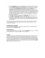
Page 15: ...your own bitmap only the bmp format is supported Use Images editing programs like MS Windows Paint to create edit bitmaps Figure 4 Set Background Image If you have a background but no longer want it s...

Page 16: ...ith the device Blue Green color icon means that the communication status is OK Red color icon means that there is no SNMP communication with the device the device is probably down in that case the hig...

Page 17: ...EL and HELP buttons 1 Clicking on the CANCEL button will close the window without sending any changes to the device 2 Clicking on the OK button will send changes if any to the device and close the win...

Page 18: ...ics image can be viewed as a graph The Ports button will open a graph window which allows seeing graphs for all the counters per selected port The Cnts button will open a graph window which allows see...

Page 19: ...such as excessive collisions where you need to adjust system parameters to improve traffic flow Click on the Spdm check box next to a desired counter to open a Speedometer graph for this counter Figur...

Page 20: ...ys Figure 11a illustrates the Input Bytes activity for port 2 Figure 11a Line Graph For more sophisticated analysis and comparison multiple line graphs up to 16 linear graphs can be included in a sing...

Page 21: ...counters that have different dimensions in one graph window for example Received Bytes and Transmitted Packets Buttons located below the graph Figure 11a allow you to obtain further information and pr...

Page 22: ...urn off the Y check box especially when graphs have peaks 3 Show in the graph Change these values to correspond to the type of statistic a graph contains For example Absolute Value number of packets R...

Page 23: ...ata from a counter to an existing bar graph default or generate a new graph Use bar graphs for comparing the relative amounts of two or more values The basic rules for configuring bar graphs are the s...

Page 24: ...Informational Please note that a lot of alarms are actually generated by SNMP Traps which are sent by different network devices Alarm Notifications In addition to an audible sound notifying you of an...

Page 25: ...bo box to Yes No for enabling disabling logging of the alarm in the Alarm Log Set the severity for each alarm by selecting the respective combo box value NOTE Alarm severities are not updated on alarm...

Page 26: ...e mal notification works Click on the Send E mail button to open Send E mail window Figure 18 Send E mail window Clicking the OK button will send the message Please note that this feature may be also...

Page 27: ...Figure 19 Remote MegaVision WEB GUI interface...

Page 28: ...IBView Window MIBView enables the user to Get the value of any object from any one of the MIBs that are listed in the mibs all file located in the application s root directory The MIB variable is disp...

Page 29: ...directory Important There is no guarantee that new MIBs will be compiled properly That is why those users who want to use this feature must have ability to analyze the output errors and understand AS...

Page 30: ...er of interface corresponds to ifIndex from MIB 2 Interface Description a textual string containing information about the interface Interface Type the type of interface distinguished according to the...

Page 31: ...s particular device The Utilization button brings up a graph window representing the interfaces utilization This window is described later in this section figure 24 Interfaces Statistics per Interface...

Page 32: ...ansmitted to a subnetwork unicast address including those that were discarded or not sent Output Non Unicast Packets the total number of packets that higher level protocols requested be transmitted to...

Page 33: ...aphs per Counter window Interfaces Utilization Window You may enter this window from 1 The Main Menu Bar under Monitor 2 The Utilization button in the Interfaces Table window 3 From the device window...

Page 34: ...graphs window This window shows the interface s utilization in percent right bar graphs and the interface s errors per second left trend graph The information is based on device Interface Table ifTab...

Page 35: ...ndow The selected device is displayed in the Device Name field but you can select any device on the map via the pull down menu Click the Intfs and Cnts buttons to open the RMON Group 1 Statistics per...

Page 36: ...at RMON Group 1 is not fully supported for this device Note the Segments utilization in percents right bars graph and segments errors per second left trend graph The information is based on RMON Group...

Page 37: ...2 History Each interface may have several corresponding entries in this table the default is two entries per interface with long and short reporting intervals The table usually contains entries for a...

Page 38: ...ted on this device You may use the Delete button in the RMON Group 2 Window Figure 30 in order to delete the undesired control entry The History Table contains history information for one interface Th...

Page 39: ...cting it in the main map via the Device Name box in the bottom right corner of Figure 30 RMON Groups 3 9 Alarms and Events You can enter this window from 1 The Main Menu Bar Monitor RMON Groups 3 9 2...

Page 40: ...le MIB II counters e g InErrors Input Errors or any MIB variable You may also refer to Interfaces Statistics per interface section earlier for more information on MIB 2 counters Sample Type Select the...

Page 41: ...nt in the Events Table see below Without one you will not be able to enter a Rising Event Index and a Falling Event Index Click on the Delete button Figure 32 in order to delete the selected Alarm Con...

Page 42: ...ally not required Press OK in the Add Event RMON Group 9 window If the Create operation fails it may mean that RMON Group 9 is not supported on this device Click on the Delete button Figure 32 to dele...

Page 43: ...ually MegaVision requires specific parameters to establish communication with a device You must supply a name and address specify communication type enter polling durations and SNMP community names In...

Page 44: ...ces available to the device for communication with the network The first interface on the list receives the highest priority for establishing communication If communication cannot be established throu...

Page 45: ...sfully established the device icon will become green If communication has not been established the device icon will become red After a device has been successfully defined it is polled at every poll i...

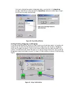
Page 46: ...Choose SUMBAP in order to add a new map submap to the current map The Describe Submap Window opens Enter a submap name in the Name field and click the OK button Figure 39 Describe Submap Window 2 The...

Page 47: ...everal operations which can make working with submaps easier cut paste and drag drop You can also move devices icons on the map with your mouse by dragging them into the desired location You can cut o...

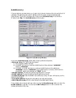
Page 48: ...C device or ROUTER 3 All SNMP or TCP IP devices Any unknown SNMP device will be added as a GENERIC device or ROUTER Any TCP IP device i e device which does not have SNMP agent will be added as TCPIP d...

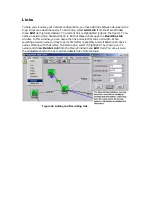
Page 49: ...it Both of these actions open the Describe Link window In this window you can name the link and select its color and width When selecting a device name you may type its first letter repeatedly to scr...

Page 50: ...ith a quick look at basic information about a device items such as product type up time device location and contact The information is retrieved via SNMP according to MIB 2 RFC 1213 specification You...

Page 51: ...y window Generic SNMP devices may send standard SNMP traps alarms and MegaVision is able to receive them There are two types of Generic SNMP Devices GENERIC and ROUTER Double click on Generic device i...

Page 52: ...itor item or via device specific menu which pops up by right mouse click on the selected device Figure 46 Services Monitor Window If any of the discovered services goes down it becomes red in the Serv...

Page 53: ...nalysis Click on the Configure Collecting button to enter the Services Configuration window Figure 47 Services Configuration Window Set the Report every field to the time interval which will be used f...

Page 54: ...s is associated with the network interface used to connect the device The first 6 digits denote the device vendor The user may assign an alias to any complete MAC address or the 6 digit vendor code Th...

Page 55: ...ning digits If there is no corresponding alias entry just the MAC address will be displayed Please note that there are some other windows besides Alias Manager which allow assigning aliases to MAC Add...

Page 56: ...larms can be logged The following data can be obtained through the management GUI General Device parameters Product Type MAC address UDP port IP Address Communication mode Gateway address Software ver...

Page 57: ...Status Communication status via wire data Port Air Link Status Communication status via Laser Data Ray Wire Link Port The type of the Wire Link Data Port Management Link Status Communication status v...

Page 58: ...such interface HP OV NNM Versions 5 x and higher allow to call WEB browser for any device icon which is located on the HP OV NNM Map This feature may be used to provide seamless GUI access to all mana...

Page 59: ...the required device icon appears Choose the icon representing the device you wish to add The cursor changes shape 3 Drag and drop the device icon to the HP OpenView map window The device icon is added...

Page 60: ...CiscoWorks must be installed before MegaVision After MegaVision installation it will start automatically when SNMPc starts Open a new map Add some devices to the map or do SNMPc Autodiscovery SNMPc w...

Page 61: ...d run SETUP EXE Follow the instructions on the screen The installation process puts a MegaVision Close icon into the Spectrum Program Group Normally this icon is not used Use it ONLY if you want to cl...

Page 62: ...efore string 3 Compare the files to the same files in the MegaVision directory If You Have Problems Starting MegaVision From The Spectrum Icon Submenu 1 In the SpectroSHELL prompt change your working...

Reviews: