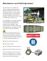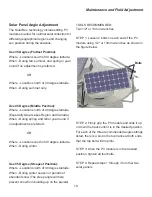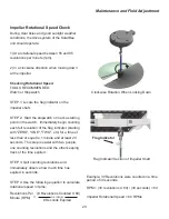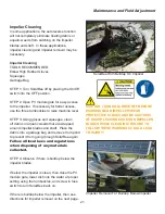
31
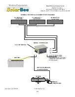
MOTOR
MOTOR
CONTROLLER
BATTERY
2
3
4
5
6
(OPTIONAL)
GRID
POWER
PV
MODULE(S)
Maintenance and Field Adjustment
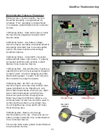
Complete Power Down Procedure
NO TOOLS REQUIRED:
STEP 1: Turn the On/Off switch to Off position.
STEP 2: Unscrew all PV module leads on the
front side of the digital controller.
STEP 3: Unscrew the on-shore (grid power)
connection on the right face, if applicable.
STEP 4: Disconnect the battery lead on the
left face. Now all power is taken away from the
electrical system.
Be certain steps 1-4 have been completed
before continuing. If this order is not followed,
component damage may occur.
STEP 5 & 6: Disconnect the motor controller
from the digital controller and from the motor if
needed.
Complete Power Up Procedure
NO TOOLS REQUIRED:
STEP 1 & 2: Connect the motor controller to
the motor and to the digital controller.
Be certain steps 1-2 have been completed
before continuing. If this order is not followed,
component damage may occur.
STEP 3: Now you are able to bring power to
boot up the system by plugging in the 4P Male
connector of the battery to the left face of the
digital controller.
STEP 4: If applicable, connect the on-shore
(grid power) 2P male connection
to the right side of the digital
controller.
STEP 5: Connect all available PV module leads
into the front face of the digital controller.
STEP 6: Turn the On/Off switch to On position.
DIGITAL
CONTROLLER
1
ON / OFF
SWITCH
MOTOR
MOTOR
CONTROLLER
BATTERY
ON / OFF
SWITCH
1
2
3
4
5
6
(OPTIONAL)
GRID
POWER
PV
MODULE(S)
DIGITAL
CONTROLLER

