background image

46

4. Hoist SolarBee From Water

TOOLS: Crane, Backhoe, or Hoist; 
3-Point Lifting Chain/Strap

Now that the SolarBee is at the pond edge 
where it can be reached, it is ready to be 
hoisted out of the water.

The following steps need to be followed when 
removing the SolarBee from the water:

STEP 1: Connect the 3-Point Lifting Chain or 
Strap to all 3 lifting points on the top frame of 
the SolarBee.  Be sure all points are securely 
attached.

STEP 2: Position the crane, back hoe, or 
hoisting equipment where it can safely reach 
and vertically hoist the SolarBee.

STEP 3: Connect to the 3-Point Lifting Chain 
or Strap and be sure everyone is clear of the 
lifting zone.

STEP 4: Hoist the SolarBee out of the water 
and pull up on a flat working surface.

STEP 5: Lower the SolarBee until the intake 
plate is close to touching the ground.  Be sure 
not to lower the machine too much to crush 
the intake plate.  Depending on the hose size, 
the machine may rest on the extended floats 
prior to the intake plate hitting the ground.  
If the intake plate is too low, then utilize 
blocks or keep the machine suspended for 
disassembly.

The SolarBee is now ready to be 
disassembled.

SolarBee Removal

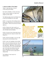
CAUTION: WHILE SOLARBEE 

IS SUSPENDED IN THE AIR, 

KEEP CLEAR BELOW AND 

IMMEDIATELY AROUND 

SOLARBEE TO AVOID BEING 

CRUSHED IN THE EVENT OF THE 

UNIT UNEXPECTEDLY DROPPING 

TO THE GROUND .  FAILURE TO 

FOLLOW THIS WARNING COULD 

LEAD TO SERIOUS INJURY!

Summary of Contents for SolarBee SB10000DM

Page 1: ...ting Specifications Model Drawing Overall Machine Dimensions Parts Identification Warranty Statement Removal Instructions Storage Instructions Installation Instructions 1 4 5 16 29 32 35 36 37 38 39 4...

Page 2: ...1 Carefully read safety information when you see any safety symbols...

Page 3: ...CES ON THE FLOAT ARM AND TURNBUCKLE STRUCTURES PRIOR TO DISASSEMBLY FAILURE TO FOLLOW THIS WARNING COULD LEAD TO SINKING THE SOLARBEE OR CAUSE SERIOUS INJURY Entanglement Hazard WARNING IF MOVING OR D...

Page 4: ...million gallons per day The machine in this lake circulates 14 0 million gallons per day The machine runs during daylight night hours entirely powered by solar energy SolarBee long distance water circ...

Page 5: ...or your application Extensive design efforts have been made to make the SolarBee easy to maintain with high quality long life parts If at any time you feel that your SolarBee is not operating at its f...

Page 6: ...s from the sun Its solar panels provide power to the onboard battery which energizes the drive system s controls and motor The new Technology allows excess solar energy to be stored during the day and...

Page 7: ...o the digital controller A bird deterrent is located directly above the PV modules to prevent bird fouling The PV modules have 3 angle settings that are set at the factory based on solar energy availa...

Page 8: ...s of the machine Each gate opens by simply removing a pin on the latch end Onboard Battery The onboard battery is located directly below the dish in a stainless steel compartment During operation the...

Page 9: ...ected by the PV modules between the brushless motor and battery 2 To serve as the main control center that operates the brushless motor There are 3 PV module connections located on the front face of t...

Page 10: ...ntrol center Due to the high frequency of communication between the motor controller and brushless motor the two components need to be located close to one another This is the primary reason for havin...

Page 11: ...quietly and smoothly It does not require any maintenance A drive shaft extends through the bottom center of the housing Shaft Coupling The shaft coupling connects the brushless motor drive shaft to t...

Page 12: ...grade oil filled Teflon freeze sleeve secured with o rings surronds the impeller shaft The freeze sleeve is free to rotate on the shaft If the water should freeze around the machine the freeze sleeve...

Page 13: ...et approximately 2 inch to 2 5 inch 5 1cm to 6 4cm below the surface of the water to achieve best flow results The distributor dish depth is set by rotating the turnbuckles located on the float arms H...

Page 14: ...the lip of the distributor dish to lower The turnbuckle and float arm structure components are constructed with robust stainless steel materials allowing the SolarBee to operate in severe environment...

Page 15: ...oats The SolarBee has 3 floats made from high density Polyethylene The floats are filled with a Polystyrene closed cell foam for long term buoyancy The floats have a uniquely designed shape to Minimiz...

Page 16: ...at plate on one of the floats The anchor chain contains swivels approximately every 15 ft 4 5m to prevent the chain from twisting and tangling A 7 1 scope is generally preferred for the length of anch...

Page 17: ...across the pond or reservoir and tied to both tether posts The SolarBee has 2 short chains running from two of the float plates on the machine out to the cable line running across the pond or reservo...

Page 18: ...cedures on the SolarBee A large expensive boat isn t necessary Our Medora Corp field teams use 12 ft 3 65m Jon boats that work fine for almost all applications It is extremely important that safety co...

Page 19: ...completely off by the bird deterrent resulting in the panel s effective surface area decreasing PV Module Cleaning TOOLS RECOMMENDED Squeegee Glass Cleaner Paper Towel or Wash Cloth STEP 1 Rinse pane...

Page 20: ...djustment is preferred OR Where Locations south of 40 degree latitude When During winter Use 55 Degree Steepest Position Where Locations north of 40 degree latitude When During winter season or period...

Page 21: ...ull revolution of the flag indicator starting with ZERO ONE TWO etc for a time of less than or equal to 1 minute and at least 20 seconds This step is easier with two people one counting revolutions an...

Page 22: ...STEP 1 Turn SolarBee off by placing the On Off switch into the OFF position STEP 2 Open PV module gate for easy access to the impeller If necessary for better access use the three turnbuckles to rais...

Page 23: ...nd brushless motor STEP 3 Observe and clean any debris located on the bottom of the impeller STEP 4 Observe and clean any debris located down in the dish where the impeller rests STEP 5 Once clean pla...

Page 24: ...arm extends out from the machine This can be done using a tape measure or locating the notch on each chain bracket for machines having a hose If using the notch on each chain bracket the water level s...

Page 25: ...member STEP 2 Use the tape measure to determine how deep the pond at the SolarBee unit STEP 3 Locate the white float ball that is on one of the floats This float ball marks the chain that is attached...

Page 26: ...ng rubber gloves pull up on the chain until the strainer is above the water If there is debris or garbage on the strainer remove it place it in a garbage bag and take it out of the pond to prevent it...

Page 27: ...ff locate the battery compartment below the SolarBee distribution dish STEP 4 Using the 13mm wrenches loosen and remove the upper bolt and locking nut This will allow the battery lid to be opened up I...

Page 28: ...g block is popped free pull up more anchor chain and pop the second mooring block STEP 4 Once both mooring blocks are loose from the bottom pull them up so they are off the bottom and tie them off the...

Page 29: ...in many cases one cannot recognize that the ice is thin around the machine For this reason it is highly recommended that the SolarBee should NOT be approached during the period of time it is frozen in...

Page 30: ...PV MODULE 3 SOLAR PANEL PV1 PV2 PV3 BATTERY ON OFF SWITCH DIGITAL CONTROLLER GENERAL ELECTRICAL SCHEMATIC FOR SOLARBEE GRID POWER BACKUP OPTIONAL CONNECTED ON OPPOSITE FACE OF CONTROLLER Main Office a...

Page 31: ...30 Maintenance and Field Adjustment...

Page 32: ...gital controller and from the motor if needed Complete Power Up Procedure NO TOOLS REQUIRED STEP 1 2 Connect the motor controller to the motor and to the digital controller Be certain steps 1 2 have b...

Page 33: ...olid green LED off or on 3 Using the LED label match your blink observations to the corresponding indication Use the information on the next two pages to proceed DC Voltage Check If a DC voltmeter is...

Page 34: ...wn due to blown fuse glass cylindrical on the Zahn Board Left side of Zahn board takes a 5 Amp Fuse Right side of Zahn board takes a 20 Amp Fuse Disconnect power before changing fuses Blown fuses may...

Page 35: ...M ERROR FOUR 4 RED BLINKS CHARGE COMM ERROR FIVE 5 RED BLINKS BATTERY OUT OF RANGE ONE 1 YELLOW BLINK HIGH MOTOR CURRENT TWO 2 YELLOW BLINKS LOW BATTERY VOLTAGE THREE 3 YELLOW BLINKS TEMP OUT OF RANGE...

Page 36: ...on Modbus RTU DB9 male connection point inside enclosure Wireless options available not included Wiring Corrosion resistant industrial cord with molded watertight connectors that are indexed to preven...

Page 37: ...36 MODEL SB10000DM 522_20160513 2016 Medora Corp Main Office and Service Center Medora Corp 3225 Hwy 22 Dickinson ND 58601 Ph 1 701 225 4495 1 866 437 8076 Fax 1 701 225 0002...

Page 38: ...37...

Page 39: ...601 Ph 1 701 225 4495 1 866 437 8076 Fax 1 701 225 0002 NO PART DESCRIPTION 01 22281100 ROTATING ASSEMBLY 02 22010027 LOWER COUPLING SLEEVE 03 14283095 SOLAR PANEL WIRED 04 18260225 FLOAT ARM ASSEMBLY...

Page 40: ...ty of the customer Terms applicable to all equipment There is no liability for any consequential damages of any type or to replace items that wear out from normal use in Medora s sole determination Al...

Page 41: ...IN NO EVENT WILL MEDORA CORPORATION OR ITS AFFILIATES BE LIABLE FOR ANY LOST PROFITS OR USE OR OTHER PUNITIVE SPECIAL EXEMPLARY CONSEQUENTIAL INCIDENTAL OR INDIRECT DAMAGES HOWEVER CAUSED ON ANY THEO...

Page 42: ...years to come SERIAL NO Medora Corporation 3225 Hwy 22 Dickinson ND 58601 1 866 437 8076 1 701 225 4495 Fax 1 701 225 0002 www medoraco com MODEL NO V Medora Corporation 3225 Hwy 22 Dickinson ND 58601...

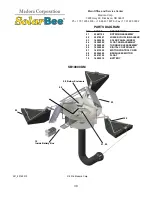
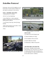
Page 43: ...Wrench Set Sizes 10mm 13mm and 19mm Required Pliers SolarBee Removal Hoisting SolarBee Out Of Water Towing SolarBee Using Small Boat Staging Area With Disassembled SolarBee Units JOB OUTLINE 1 Locate...

Page 44: ...t it out of the water and 3 disassemble it into its major componets for transportation and storage The following considerations should be made when choosing a removal and staging area Crane or Hoist E...

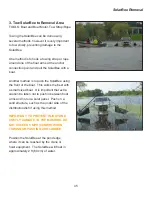
Page 45: ...e connected to the anchor chain or tether cable to maintain proper positioning when the SolarBee is re installed GPS technology can be used to mark position if anchoring or tethering removal is requir...

Page 46: ...SolarBee using the front of the boat This works the best with a small sized boat It is important that extra caution be taken not to push in between float arms and not on a solar panel Push on a solid...

Page 47: ...and be sure everyone is clear of the lifting zone STEP 4 Hoist the SolarBee out of the water and pull up on a flat working surface STEP 5 Lower the SolarBee until the intake plate is close to touchin...

Page 48: ...elow the dish STEP 3 Once the hose is removed turn in the turnbuckles until the core unit rests on the ground and the floats are slightly suspended in the air STEP 4 Remove the turnbuckles from the co...

Page 49: ...e two panel gates not covering the digital controller and place two floats within the core unit as shown in the photo Close up the panel gates One float will have to be stored separately TIP 2 Stack t...

Page 50: ...ed Repeat this charging once every two months and just prior to re installing the machine in the spring UNSHELTERED OR UNSHADED STORAGE If you plan to store the Solarbee unit where it will receive sun...

Page 51: ...mm 13mm and 19mm Required Pliers SolarBee Installation Hoisting SolarBee Out Of Water Towing SolarBee Using Small Boat Staging Area With Disassembled SolarBee Units JOB OUTLINE 1 Locate Staging and De...

Page 52: ...major components 2 lowering SolarBee into the water and 3 towing into position from The following considerations should be made when choosing a staging and deployment area Crane or Hoist Equipment Ac...

Page 53: ...t Another method is to push the SolarBee using the front of the boat This works the best with a small sized boat It is important that extra caution be taken not to push in between float arms and not o...

Page 54: ...hose chain STEP 3 Using the correct startup order power up the SolarBee unit STEP 4 If the SolarBee contains leg extensions add these at this time STEP 5 Adjust all turnbuckles to achieve the proper...

Page 55: ...ed Service and Installation Technicians are trained in Confined Space Fall Protection and other related subjects as required by OSHA to perform the necessary work to install or remove SolarBee equipme...

Reviews: