background image

44

Service Manual

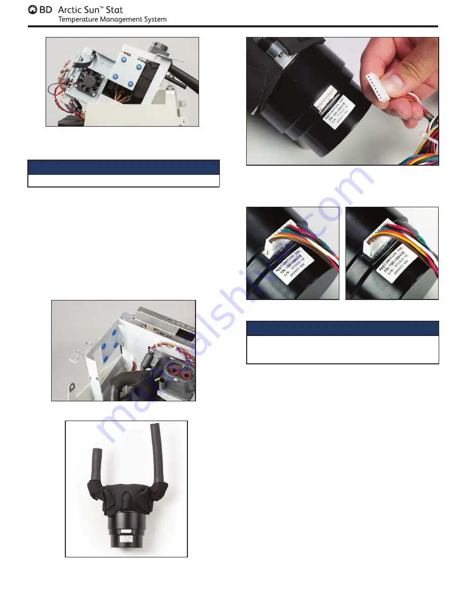
Fig 8-43 Lift up upper bracket (step 5)

Tools and Supplies required:

• 

Flat blade screwdriver

1.  Lift upper bracket to allow access to the pump per 

step 8.17. 

2.  Disconnect the cable that connects the Mixing 

Pump to the I/O Board. 

3.  Using a flat blade screwdriver, remove the four (4) 

mounting screws that secure the pump leaving 

cable ties intact. 

4.  Carefully remove the Mixing Pump and replace.

Note

: When re-connecting cable to pump motor, ensure 

that the connector is correctly seated, with no 

exposed pins on either side (see Figure 8-46).

Fig 8-44 Remove mounting screws then remove mixing pump

Fig 8-45 Mixing Pump

8.18 Replace Mixing Pump

Fig 8-46 Illustration of pump connector prior to being connected

(above), connected but seated incorrectly with one pin exposed

(below left), and seated correctly (below right)

8.19 Replace Circulation Pump

Tools and Supplies required:

•  Flat blade screwdriver

•  Small flat blade screwdriver

•  Wire cutters

1.  Lift upper bracket to allow access to the pump per 

step 8.17.

2.  Disconnect the cable that connects the Circulation 

Pump to the I/O Board. 

3.  Using a small flat blade screwdriver, loosen the 

hose clamp that secures the tubing to the back of 

the manifold. Slide hose clamp backwards onto 

tube and then remove tube from manifold.

4.  Locate the flowmeter cable and disconnect it from 

J2 on the I/O Circuit card. Cut the two wire ties that 

secure the flowmeter cable to the upper bracket.

5.  Using a flat blade screwdriver, remove the four 

(4) mounting screws that secure the pump to the 

upper bracket.

6.  Carefully remove the Circulation Pump and replace.

Note

: When re-connecting cable to pump motor, ensure 

that the connector is correctly seated, with no exposed 

pins on either side (see Figure 8-46).

Summary of Contents for Arctic Sun Stat

Page 1: ...Arctic Sun Stat Temperature Management System SERVICE MANUAL...

Page 2: ......

Page 3: ...5 Replace Front Case Assembly Components 36 8 6 Replace the Control Panel Assembly 37 8 7 Removing Replacing Circuit Cards from Card Cage 37 8 8 Replace the Panel ESD Board 39 8 9 Replace the Connect...

Page 4: ...en connected to an equivalent receptacle marked hospital use or hospital grade When using the Arctic Sun Temperature Management System note that all other thermal conductive systems such as water blan...

Page 5: ...under the ArcticGel pads often especially those at higher risk of skin injury Skin injury may occur as a cumulative result of pressure time and temperature Possible skin injuries include bruising tear...

Page 6: ...trolling of patient temperature should only be performed under the supervision of a qualified healthcare professional Setup Procedure Unpack 1 Unpack the Arctic Sun Temperature Management System Contr...

Page 7: ...abled 16 Rewarming Hypothermia Screen Patient Pad Selection Screen Once the therapy has been selected the user will be prompted with the Pad Selection screen Select the appropriate pad type based on t...

Page 8: ...nstallation of the Control Module 1 Power On the Control Module 2 From the patient Therapy Selection screen press the button next to Hypothermia to display the Hypothermia therapy screen Select the ad...

Page 9: ...sists of 4 heating rods The heating element within each rod is in series with a non resettable thermal fuse which protects each rod against an over temperature condition Inlet Outlet Manifold connects...

Page 10: ...d meters it into the Chiller Tank Cold water overflows from the Chiller Tank into the Circulation Tank The speed of the mixing pump is dependent upon the flow rate through the circulation tank and the...

Page 11: ...0 uses whichever occurs first as indicated by system display Clean the External Surfaces After use the external surfaces of the Arctic Sun Temperature Management System may be a potential biohazard Th...

Page 12: ...ion protocol To prevent possible discoloration do not use iodine based solutions such as Betadine on any part of the machine For questions on device cleaning and disinfection of external surfaces cont...

Page 13: ...resent and that the rings make an intact seal with the Fluid Delivery Line System Diagnostics Select the System Access button on the Normothermia therapy or Hypothermia therapy screen to access System...

Page 14: ...The USB data port is to be used only with a standalone USB flash drive Do not connect to another mains powered device during patient treatment Patient Data Fields Parameter Units Date MM DD YY Time H...

Page 15: ...indicated on the display screen Calibration instructions are stored in the device and can be accessed from the calibration screens on the Advanced Setup Screen Calibration should be done only by trai...

Page 16: ...o the local requirements From the Advanced Setup screen press the button to the right of the Date Format parameter Use the Up and Down arrows to select the date format Range MM DD YY DD MM YY DD MM YY...

Page 17: ...n of power the device will issue alarm 45 There are two types of conditions Medium Priority Alarms and Low Priority Alarms Non Recoverable Alarms If an Alarm condition occurs that prevents proper use...

Page 18: ...r leak or low flow Wait a minimum of 45 seconds for the air to clear the line and then check to see if the flow has increased If faulty pad found replace faulty pad 5 To check whether a valve is leaki...

Page 19: ...hat may affect cooling Are the machine vents blocked Is the room temperature too high Is the oxygen heated Are there hot lights or heating blankets on the patient Remove any impediments Monitor water...

Page 20: ...is not working Call BD Customer Support If the water temperature increases to the commanded temperature the water heating system is working 5 Verify Patient Control System Performance Place system bac...

Page 21: ...e and temperature cable is secure 4 Check that the connection between the temperature cable and the Temp In 1connector is secure 5 Check the integrity of the temperature cable Flex the cable to check...

Page 22: ...ntal conditions that may affect cooling Are the machine vents blocked Is the room temperature too high Is the oxygen heated Are there hot lights or heating blankets on the patient Remove any impedimen...

Page 23: ...emperature the water heating system is not working Call BD Customer Support 5 Verify Patient Control System Performance Place system back into the patient control mode Monitor water temperature and pa...

Page 24: ...em is unable to internally check the calibration of the Patient Temperature 2 channel within 1 0 C when the system is in Manual Control mode Patient Temperature 2 channel is made inactive 1 Power syst...

Page 25: ...ority Alarm One or more of the entries into the system event log is invalid The system event log is used by clinical engineering personnel for product service This issue does not affect the performanc...

Page 26: ...ng is activated The system is not in Manual Control mode The high water temperature limit and low water temperature limits are set correctly See VI Operation Guide Therapy Settings High Water Limit or...

Page 27: ...ing which may or may not be visible Consider administration of additional medication for shivering control adequate for the patient weight and magnitude of shivering follow physician orders institutio...

Page 28: ...omer Support 80 Non Recoverable System Error Medium Priority Alarm The control processor failed to detect a simulated water temperature fault 1 Turn Control Module Off Wait 30 seconds and turn Control...

Page 29: ...he use of an esophageal temperature probe when patient target temperature control below 33 C is set Place esophageal temperature probe in patient and connect to the Temp In 1 cable on the back of the...

Page 30: ...Make Clinical Decision If all of the above considerations have been addressed and the patient still has not reached target temperature the physician and nursing staff make a clinical decision to limi...

Page 31: ...ypothermia Therapy Setting screen With the device at room temperature power the device on wait 5 minutes and check the Chiller temperature T4 on the Diagnostic screen This temperature should be below...

Page 32: ...Fluid Delivery Line and place thumb over the left port Repeat the test in step 3 To confirm there are no leaks in the Fluid Delivery Line valves attach a shunt tube to any set of valves and initiate M...

Page 33: ...moval and replacement of the component A list of spare parts and accessories is located in Appendix D In general reverse the order of removal to install a replacement component Please note any special...

Page 34: ...edivance com manuals Fig 8 2 Control Module Front inside view AC Breaker Harness Manifold Harness Card Cage Main Harness Pump Connections Control Panel Connection Chiller Power Connection Chiller Evap...

Page 35: ...32 Service Manual Fig 8 3 Control Module Right inside view Transmission Interface Module Connector Panel Bracket I O Manifold Chiller Pump Drain Cup Chiller Condenser Hot Gas Bypass Valve...

Page 36: ...33 English The current Service Manual can be found at www medivance com manuals Fig 8 4 Control Module Left inside view Heater Harness Connection AC Breaker Harness Connection Chiller Fan...

Page 37: ...rd Identification Fig 8 6 Power Supply Fig 8 7 AC PCB The following two 2 Circuit Cards are mounted on the lower bracket next to the Chiller Condenser Input Output I O Circuit Card Isolation Circuit C...

Page 38: ...lade screwdriver 13 16 21mm wrench 9 16 14mm wrench 7 16 11mm wrench 1 16 1 5mm hex key Wire cutter small Needle nose pliers Total Drain A total drain activates the pumps to remove residual water It i...

Page 39: ...the zip tie around the communications connector and disconnect both communications and power connections from the top of the card cage Fig 8 11 Disconnect cables from control panel step 2 Fig 8 12 Rem...

Page 40: ...y then remove the bracket assembly with harnesses attached from the control panel 7 Grasp new Control Panel and slide into the front panel by first aligning the panel just below the screws in the hand...

Page 41: ...ircuit Card perform a calibration see Chapter 9 Fig 8 17 Disassemble Connector Panel from Chiller Frame Fig 8 18 Suspend Connector Panel by wiring harness Fig 8 19 I O Circuit Card Connections Fig 8 2...

Page 42: ...the new panel ESD board and secure with the four 4 phillips head screws then reattach the blue temp connector PCB cable to the back of the board 7 Reinstall the Lemo nuts for PT1 PT2 and Temp out on t...

Page 43: ...ly to the device and connect the blue temp connector PCB cable to the isolation board Fig 8 25 Placement of AC Breaker Harness Connections Fig 8 26 Connector Panel Bracket Assembly 3 Assemble the new...

Page 44: ...e 12 O clock position and replace the nuts to the backsides of valve 5 Connect tubes to backside of drain valve and refasten drain cup to chiller frame with the hex screws Fig 8 31 Remove tubing from...

Page 45: ...he solenoids are installed in the correct locations see fig 8 37 Note When reinstalling the solenoids if they are not installed properly it will prevent the device from functioning properly 7 Remount...

Page 46: ...talled with the upper right screw on the circuit card 9 Reinstall the jumper to the AC PCB and connect the two 2 lower main harness connections on the power supply board Fig 8 39 Placement of power in...

Page 47: ...pin exposed below left and seated correctly below right 8 19 Replace Circulation Pump Tools and Supplies required Flat blade screwdriver Small flat blade screwdriver Wire cutters 1 Lift upper bracket...

Page 48: ...he harness from J1 on the AC PCB 3 Remove the black foam covering the two 2 hex head screw securing the heater to the lower bracket Then using a 7 16 11mm nut driver remove the two 2 screws Attention...

Page 49: ...require the removal of the Internal Components via the following steps Attention Ensure the unit is drained prior to completing any repairs in this section 1 Loosen the two 2 hose clamps that hold the...

Page 50: ...acket 4 Carefully pull down on the chiller pump to remove it from the tank 5 Place two 2 new O rings in the slots on the chiller pump outlet as shown Ensure that the O rings sit completely inside the...

Page 51: ...d carefully install the thermistors into the tank Tighten the thermistors finger tight plus turn ensuring washer is compressed between the tank and sensor housing Note Verify the proper locations of T...

Page 52: ...cessful completion of a calibration check a report is displayed showing a pass or fail status of all parameters checked 9 3 Calibration Setup 1 Remove fluid delivery line by flipping latch from right...

Page 53: ...tor to arrange for disposal Parameter Specification Therapy Modes Normothermia Control Patient Rewarming Hypothermia Cooling Rewarming Heater Maximum Power 814 Watts Circulating Fluid Sterile Water wi...

Page 54: ...ce no 5 1 7 Medical Devices Symbols to be used with medical device labels labelling and information to be supplied Serial number Indicates the manufacturer s serial number so that a specific medical d...

Page 55: ...ectrical Equipment in Medical Practice Draining emptying To indicate the emptying of any vessel or container of liquid or produce for example draining of oil tanks draining ink reservoirs or emptying...

Page 56: ...e the content of the package is fragile and that the package must be handled with care IEC TR 60878 Reference no 0626 Graphical Symbols for Electrical Equipment in Medical Practice Keep away from rain...

Page 57: ...used when filling the ARCTIC SUN Stat Temperature management system Control Module N A N A N A Identifies Patient Temperature 1 the patient temperature probe input for monitoring and control N A N A N...

Page 58: ...should assure that it is used in such an environment Emissions test Compliance Electromagnetic environment guidance RF emissions CISPR 11 Group 1 The Arctic Sun Temperature Management System uses RF...

Page 59: ...00 iDEN 820 CMDA 850 LTE band 5 Pulse mod 18 Hz 2 0 3 28 870 930 1720 1700 1990 GSM 1800 CDMA 1900 GSM 1900 DECT LTE band 1 3 4 25 UMts Pulse mod 217 Hz 2 0 3 28 1845 1970 2450 2400 2570 Bluetooth WLA...

Page 60: ...SD Board 404121 00 Connector Panel Assembly 404122 00 Control Panel Strap 404123 00 Fluid Drain Door Assembly 404124 00 Bracket Power Cord RoHS 404130 00 RIM Back Panel 404131 00 PCB Connector Cable 4...

Page 61: ...58 Temperature In Cables Temperature Out Cables Service Manual Appendix E Temperature Cables...

Page 62: ...am 3 Place top support on top of the device with the foam side down 4 Add top shelf to the top of the support and place any accessories being shipped with the unit into the shelf 5 Install sleeve over...

Page 63: ...ss or failure of the software install If software install fails at any point a red X will appear and process will not reach 100 5 Screen will go blank after completion wait for a mimum of 1 minute the...

Page 64: ...LT FREE AND OCCASIONAL PERIODS OF DOWNTIME OCCUR BARD DOES NOT GUARANTEE THE USE OF THE EQUIPMENT AND ITS CONNECTIVITY FEATURES WILL BE UNINTERRUPTED TIMELY SECURE OR ERROR FREE OR THAT CONTENT LOSS W...

Page 65: ...l Sequence Number 1 2 3 4 5 Initialized at power up 3 Patient Temperature 1 C 0 if probe not connected 4 Patient Temperature 2 C 0 if probe not connected 5 Patient Target Temperature in Auto Mode C re...

Page 66: ...63...

Page 67: ...p 720 880 5400 Fax lou customerservice bd com PK2800349 02 2021 2021 BD BD and the BD Logo are trademarks of Becton Dickinson and Company Bard ArcticGel Arctic Sun Medivance and Simply Advanced are tr...

Reviews: