background image

E N G L I S H

23

8.5 Removing / Replacing Circuit Cards from Card Cage

To access the cards in the card cage, remove the back panel and 

the outer shell as shown in Steps 8.3 and 8.4. 

Caution: Observe electrostatic discharge control procedures 

when handling circuit cards.

A) Input / Output Circuit Card

Tools and supplies required:

•    wire cutters

•   1/16” Allen wrench / hex key

•   flat blade screwdriver

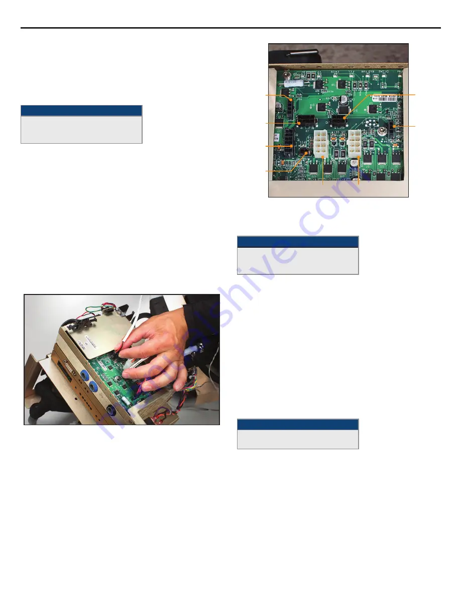
1.  Carefully disconnect each of the eight cables connected to 

the card, releasing each locking tab before pulling. These 

connections are illustrated in Fig. 8-15.

2.  Clip cable ties with wire cutters as needed.

3.  When re-connecting the connections after repair, check labels 

on J6 and J4 connectors to ensure correct connections. 

4.  Remove the Allen head screw on the right of the I/O Circuit Card 

face plate.

5.  Slide a screwdriver beneath the I/O Circuit Card to gently pry it 

away from its base.

6.  Carefully pull the circuit card outward to release it from the slots 

it sits in.

7.  When replacing the circuit card, ensure that the card fits into the 

retaining grooves on either side of the card cage. 

8.  After replacing the I/O Circuit Card, perform a calibration (see 

Chapter 9).

Fig. 8-14 Unplug connections from I/O Card (Step 1)

Fig. 8-15 I/O Circuit Card connections

B) Isolation Circuit Card

Tools and supplies required:

•   Phillips head screwdriver 

•   1/16” hex key

•   flat blade screwdriver

1.  Remove the Allen head screw on the right of the Isolation Circuit 

Card face plate.

2.  Slide a screwdriver beneath the Isolation Circuit Card to gently 

pry it away from its base.

3.  Carefully slide the circuit card out of the card cage until the 

card protrudes approximately one inch to expose the cable 

connecting this card to the top of the card cage.

4.  Remove the screws holding the cable that connects this card to 

the top of the card cage. 

5.  Carefully pull the circuit card outward to release it from the 

grooves it sits in. 

6.  When replacing the circuit card, ensure that the card fits into the 

retaining slots on either side of the card cage.

7.  After replacing the Isolation Circuit Card, perform a calibration 

(see Chapter 9).

C) Processor Circuit Card

Tools and supplies required:

•   1/16” hex key

•   flat blade screwdriver

1.  Remove the Allen head screw on the right of the Processor 

Circuit Card face plate.

2.  Slide a screwdriver beneath the Processor Circuit Card to gently 

pry it away from its base.

3.  Carefully pull the circuit card outward to release it from  

the grooves. 

4.  When replacing the circuit card, ensure that the card fits into the 

retaining slots on either side of the card cage. 

5.  After replacing the Processor Circuit Card, perform a calibration 

(see Chapter 9). 

J6 Circulation Pump   J4 Mixing Pump

J10

T1, T2, T3 

Temperature 

Sensors

J2

Flowmeter

J5

Chiller

Power

J8

Level

Sensor

J9

Manifold

Harness

J8

Card 

Cage 

Fan

Summary of Contents for ARCTIC SUN 5000

Page 1: ...S E R V I C E M A N U A L SimplyAdvancedTM TEMPERATURE MANAGEMENT SYSTEM ...

Page 2: ...ve Back Panel 21 8 4 Remove Outer Shell 22 8 5 Removing Replacing Circuit Cards from Card Cage 23 8 6 Replacing Upper Components 24 8 7 Removing Internal Components from Chiller Frame 25 8 8 Separating the Internal Components into Two Sections 26 8 9 Replacing Mixing Pump 27 8 10 Replacing Circulation Pump 28 8 11 Replacing AC Chiller Pump 29 8 12 Replacing DC Chiller Pump 30 8 13 Replacing Heater...

Page 3: ... Strategy 2 The operator must continuously monitor patient temperature when using Manual Control and adjust the temperature of the water flowing through the pads accordingly Patient temperature will not be controlled by the Arctic Sun Temperature Management System in Manual Control Due to the system s high efficiency Manual Control is not recommended for long duration use The operator is advised t...

Page 4: ...rial solutions or other agents to pool underneath the ArcticGel Pads Urine and antibacterial agents can absorb into the pad hydrogel and cause chemical injury and loss of pad adhesion Replace pads immediately if these fluids come into contact with the hydrogel Do not place ArcticGel Pads over an electrosurgical grounding pad The combination of heat sources may result in skin burns If needed place ...

Page 5: ...perature Trend Indicator G System Monitoring area H Water Temperature I Water Flow Rate J Reservoir Water Level K Therapy Graph L Manual Control button if enabled M Empty Pads button N Fill Reservoir button O Therapy Selection Screen Lock button P Temperature Units button if enabled Q Stop button R Help button Fill Reservoir 1 Fill the reservoir with sterile or distilled water only 2 Four liters o...

Page 6: ...Patient Therapy Selection screen press the Hypothermia button to display the Hypothermia therapy screen 3 From the Hypothermia therapy screen press the Manual Control button to open the Manual Control window 4 Use the Up and Down arrows to set the Manual Control water target temperature to 40 C and the duration to 30 minutes 5 Press the Start button to initiate Manual Control Allow at least 3 minu...

Page 7: ...rers temperature probes In addition temperature out cables can be purchased to allow output of patient temperature to an external monitor Please refer to the Temperature Cables in Appendix C The Mains Voltage Circuit Card located below the Supply Tank Includes electromechanical relays to control mains power to the chiller and heater Also includes solid state relays to control power to each of the ...

Page 8: ...ion Pump and returned through the Circulation Tank to the Supply Tank Electronic Control System The electronic system consists of two independent subsystems control and monitor The control subsystem is responsible for delivering therapy to the patient The monitor subsystem confirms the safe operation of the control subsystem Each subsystem has an independent microprocessor audio alarm and both wat...

Page 9: ... 28 C and the duration to 30 minutes 5 Connect a shunt to a set of fluid delivery line ports 6 Press the Help button and then press the Help Index button Select the topic Maintenance and Service and sub topic System Diagnostics then press the Display button Verify that inlet pressure is 7 0 2 7 Repeat on all valves If inlet pressure is out of range replace the two valves that the shunt is connecte...

Page 10: ...must respond to the fault and be verified by the opposing safety system If either safety systems do not respond appropriately either an alarm 80 or 81 will be issued Contact Customer Support Non Recoverable Alarms If an Alarm condition occurs that prevents proper use of the device or proper patient treatment such as the five main safety alarms discussed above the system is placed into Stop mode an...

Page 11: ...ent control mode e g Control Patient Cool Patient or Rewarm Patient 09 Patient Temperature 1 Above High Patient Alert In Normothermia Therapy The Patient Temperature 1 reading is above the High Patient Alert setting in Normothermia Settings In Hypothermia Therapy The Patient Temperature 1 reading is above the High Patient Alert setting in Hypothermia Settings 10 Patient Temperature 1 Low The Patie...

Page 12: ...ystem is in Manual Control mode 21 Patient Temperature 2 High The Patient Temperature 2 reading is above 39 5 C 103 1 F and the water temperature is above 39 5 C 103 1 F and the system is continuing to warm the patient while in a patient control mode e g Control Patient Cool Patient or Rewarm Patient 22 Patient Temperature 2 Above High Patient Alert In Normothermia Therapy The Patient Temperature ...

Page 13: ...3 5 C 38 3 F 36 Water Temperature High The secondary outlet water temperature is above 44 C 111 2 F 37 Water Temperature High The secondary outlet water temperature is above 43 C 109 4 F 38 Water Temperature Low The secondary outlet water temperature is below 3 0 C 37 4 F 40 Unable to Maintain Stable Water Temperature In Manual Control mode the system is unable to control the water temperature wit...

Page 14: ...rocessor 67 Non Recoverable System Error Unable to disable pump power Monitor processor 71 Non Recoverable System Error Primary outlet water temperature sensor out of range high resistance 72 Non Recoverable System Error Primary outlet water temperature sensor out of range low resistance 73 Non Recoverable System Error Secondary outlet water temperature sensor out of range high resistance 74 Non R...

Page 15: ...emperature tracks real time core temperature changes more closely than bladder or rectal temperature Due to this lag time when using bladder or rectal temperature sites actual patient core temperatures may be lower than measured Therefore the use of esophageal temperature is recommended for patient temperature control below 33ºC 110 Data File Not Readable The data file which contains the system de...

Page 16: ...oad feature is available from the Advanced Settings screen The following are the most common issues and methods of resolution 7 3 1 Device Not Controlling Patient Temperature The Arctic Sun 5000 Temperature Management System has a sophisticated control algorithm which calculates the appropriate water temperature based on a comparison of the patient s actual temperature versus the programmed target...

Page 17: ...nifold and repeat fill process 7 3 5 Control Panel Will Not Power On To verify proper operation of the Control Panel perform the following steps Check that mains power is available by ensuring the amber light is lit on the power switch Remove the back panel and shell Check connection at top of card cage to Control Panel and verify the connection is seated properly 7 3 6 Low Flow Alarm If the devic...

Page 18: ...ocedure for removal and replacement of the component An abbreviated list of spare parts and accessories is located in Appendix B For parts not listed contact Medivance Technical Support In general reverse the order of removal to install a replacement component Please note any special instructions to the contrary Caution Observe precautionary electrostatic discharge control procedures ESD when work...

Page 19: ...nt inside view Card Cage Main Harness Pump Connections Control Panel Connection Chiller Power Connection Chiller Evaporator Chiller Frame Compressor Manifold Harness Level Sensor Cable Flowmeter Cable A C Breaker Harness Tank Heater Power Cables ...

Page 20: ...A S 5 0 0 0 S E R V I C E M A N U A L 18 Fig 8 3 Control Module right inside view Card Cage Chiller Frame Inlet Outlet Manifold Chiller Pump Chiller Fan Chiller Evaporator Hot Gas Bypass Valve ...

Page 21: ...s controlling all machine processes are found in two areas 1 the card cage located at the top of the internal components and 2 mounted to the lower part of the frame Card Cage Chiller Frame Evaporator Tank Chiller Compressor Heater Cables Connection A C Harness Connection ...

Page 22: ...Module Fig 8 7 Mains Voltage Circuit Card Fig 8 5 Card cage circuit card identification Input Output IO Circuit Card Isolation Circuit Card Processor Circuit Card Power Circuit Card The following two circuit cards are mounted on the lower part of the frame ...

Page 23: ...some moisture present as you disassemble the unit Fig 8 8 Passive drain Total Drain A total drain activates the pumps to remove residual water It is essential to perform this process if the device is to be shipped or if the hydraulic components are to be removed 1 After completing a Passive Drain above power on the Control Module 2 Go to the Advanced Setup screen from the Patient Therapy Selection...

Page 24: ...rizontal slot on the front located a few inches below the Control Panel gently rock the shell forward The Outer Shell will slide off Set it down a few inches away from the frame 3 There are two cable harnesses connecting the control panel on the shell to the top of the card cage Disconnect these at the card cage Fig 8 11 Remove 4 bolts Step 1 Fig 8 12 Cable harnesses to be removed Step 3 Fig 8 13 ...

Page 25: ...equired Phillips head screwdriver 1 16 hex key flat blade screwdriver 1 Remove the Allen head screw on the right of the Isolation Circuit Card face plate 2 Slide a screwdriver beneath the Isolation Circuit Card to gently pry it away from its base 3 Carefully slide the circuit card out of the card cage until the card protrudes approximately one inch to expose the cable connecting this card to the t...

Page 26: ...ng each locking tab before pulling When replacing these connections tuck the wires into place against the foam 5 When replacing the circuit card ensure that the card fits into the retaining slots on either side of the card cage 8 6 Replacing Upper Components Tools and supplies required Flat blade screwdriver small flat blade screwdriver wire cutters 1 Remove the four bolts on the back of the devic...

Page 27: ... flat blade screwdriver to pop the snap fitting open Use pliers to reclose the snap fitting upon reassembly If device is equipped with a DC pump from the left side of the control module remove black molded tubing connecting chiller pump to chiller evaporator Use a small flat head screwdriver to loosen and disconnect two clamps Discard them 4 From the front of the Control Module place one hand unde...

Page 28: ...ion Pump and Mixing Pump and the other the Heater and tank Tools and supplies required 7 16 nut driver wire cutter 1 Remove the four bolts as shown see Fig 8 25 and Fig 8 26 2 Slide the two sections apart 3 Disconnect the AC Breaker Harness cutting cable ties as necessary Fig 8 24 Internal components prior to being separated into two sections front view Fig 8 25 Internal components rear view circl...

Page 29: ...nternal components from the Chiller frame and separate them into two sections Steps 8 6 8 7 or 8 8 2 Disconnect the cable that connects the Mixing Pump to the I O Board When re connecting ensure that the connector is correctly seated with no exposed pins on either side see Figure 8 32 3 Using the screwdriver remove the four mounting screws 4 Leave cable ties intact 5 Carefully remove the Mixing Pu...

Page 30: ...e cutters 1 Remove internal components from the Chiller frame and separate them into two sections Steps 8 6 8 7 or 8 8 2 Disconnect the cable that connects the Circulation Pump to the I O Board 3 Using the screwdriver loosen the four blue circled screws on the brass plate that is part of the frame until the pump is loose 4 Use the small flat blade screwdriver to pop the snap fitting open 5 Careful...

Page 31: ... power connector from the Mains Voltage Circuit Card 3 Using the 5 16 nut driver remove the ground connection by unscrewing and removing the nut shown in Figure 8 33 4 Remove the two bolts on either side of the Chiller Pump 5 Remove the Chiller Pump 6 Use the small flat blade screwdriver to pop open the clamp connecting the Chiller Pump tubing to the drain port Use pliers when reconnecting 7 When ...

Page 32: ...nal components Steps 8 6 8 7 or 8 8 2 Using the wire cutters cut the cable tie to free up chiller pump power supply connectors and disconnect cables from AC circuit board 3 Loosen chiller pump clamp and remove tube from drain valve 4 Remove two 5 16 bolts securing chiller pump to frame 5 Pull chiller pump assembly from device 6 When reinstalling DC chiller pump place two O rings on inlet side and ...

Page 33: ...tions Steps 8 6 8 7 or 8 8 2 Using the wire cutters cut the cable ties holding the cable to the frame 3 Remove the two bolts on either side of the black foam covering the Heater 4 Carefully remove the Heater unit 5 When replacing the Heater ensure that the orange rubber tab faces the back of the unit It is important that the tab is horizontal and not bent Fig 8 45 Heater Fig 8 46 Tank and Heater w...

Page 34: ...be from the pump 5 When installing a new Flowmeter note that there is a white arrow on the Flowmeter that indicates direction of flow It needs to be pointed away from the pump 6 Re insulate the Flowmeter Fig 8 49 Flowmeter and cable Fig 8 50 Flowmeter with arrow indicating direction of flow same direction as Circulation Pump output 8 15 Replacing Control Panel Tools and supplies required 7 16 nut ...

Page 35: ...erature Sensor Harness The Tank Temperature Sensor Harness connects the Chiller Pump with the tank Tools and supplies required wire cutters 1 Remove internal components from the Chiller frame and separate them into two sections Steps 8 6 8 7 or 8 8 2 Remove insulation from the point at which the thermometer enters the tank 3 Remove the associated cable ties 4 Remove the piece of insulation tape th...

Page 36: ...anifold to the brass frame 3 Using small flat blade screwdriver pop open the two clamps connecting the tubing to the Manifold opening the clamp closest to the metal frame first 4 The Manifold Harness connects to three Solenoids FV Fill Valve BV Bypass Valve and VV Vent Valve 1 Thermistor and 1 Pressure Transducer Medivance ships replacement Manifold Harnesses complete with the three valve stems an...

Page 37: ... the thermistor 7 When reinstalling connect the valve stems first then the solenoids then the pressure transducer then the thermistor 8 When reinstalling the Manifold Harness note that there are labels on the harness identifying the solenoids FV BV VV If the solenoids are not in the proper position as shown the device will not work properly Fig 8 59 Fig 8 60 Manifold Assembly 8 20 Replacing Level ...

Page 38: ... Card Fig 8 63 Power Module Fig 8 64 Power Module in position with connections in place 8 22 Replacing Mains Voltage Circuit Card Tools and supplies required pliers Phillips head screwdriver 1 Disconnect the AC Breaker Harness 2 Disconnect jumper to Power Circuit Card 3 Disconnect Chiller Pump power 4 Disconnect two connectors that go to power inlet module plug 5 Disconnect the Heater power cable ...

Page 39: ...or AC breaker Figure 8 68 AC Breaker Harness connections to AC breaker 8 24 Installing Transmission Interface Module Tools and supplies required 3 8 Socket wrench 1 Remove the bolt from the upper left of the back of the device 2 Place the bracket on the back of the device and use bolt provided to secure 3 Insert transmission interface module TIM into bracket 4 Connect USB cable to left side of mod...

Page 40: ...heck confirms the device flow ability to heat and cool and the temperature sensing systems are all within specification During the calibration check errors may be displayed with diagnostic information assisting with performance or calibration issues After successful completion of a calibration check a report is displayed showing a pass or fail status of all parameters checked 9 3 Calibration Setup...

Page 41: ...CLASS I mobile device Type BF IPX0 and Mode of Operation Continuous per classification scheme of IEC 60601 1 The Arctic Sun Temperature Management System Control Module meets both the electromagnetic interference and susceptibility requirements of IEC 60601 1 and is compatible with other equipment that also conforms to that standard There is no known failure mode in the Arctic Sun Temperature Mana...

Page 42: ...ues derived from testing in simulated use Patient Temperature Control Range 32 C to 38 5 C 89 6 F to 101 3 F 0 1 C F increments Water Temperature Display Range 3 C to 45 C 37 4 F to 113 0 F 0 1 C F increments Water Temperature Control Range Manual 4 C to 42 C 39 2 F to 107 6 F 1 C F increments High Water Temperature Limit 36 C to 42 C 96 8 F to 107 6 F 1 C F increments Low Water Temperature Limit ...

Page 43: ...r component The maximum temperature of this internal component allowed by the protective system is also listed Indicates that only sterile or distilled water should be used when filling the Arctic Sun Temperature Management System Control Module 1 Identifies Patient Temperature 1 the patient temperature probe input for monitoring and control 2 Identifies Patient Temperature 2 the patient temperatu...

Page 44: ...o cause any interference in nearby electronic equipment RF emissions CISPR 11 Class A The Arctic Sun 5000 Temperature Management System unit is suitable for use in all establishments other than domestic establishments and those directly connected to the public low voltage power supply network that supplies buildings for domestic purposes Harmonic emissions IEC 61000 3 2 Class A Voltage fluctuation...

Page 45: ...c site survey should be considered If the measured field strength in the location in which the Arctic Sun 5000 Temperature Management System unit is used exceeds the applicable RF compliance level above the Arctic Sun 5000 Temperature Management System unit should be observed to verify normal operation If abnormal performance is observed additional measures may be necessary such as re orienting or...

Page 46: ...ntal Europe 733 01 Power Cord UK Ireland 733 02 Power Cord Australia New Zealand 733 03 Power Cord Mainland China 733 04 Memory Stick 775 00 Transmission Interface Module T I M Kit 760 00 Transmission Interface Module T I M 761 00 RS232 Cord 762 00 Transmission Interface Module T I M Bracket Assembly 763 00 Cables and Accessories Spare Parts Appendix D Spare Parts and Accessories Caster with Brake...

Page 47: ...E N G L I S H 45 Appendix E Temperature Cables Temperature In Cables Temperature Out Cables ...

Page 48: ...dvanced Setup screen b Press the Start button next to Total Drain and follow the instructions 2 Place the Arctic Sun 5000 Temperature Management System onto the white foam attached to the pallet and center the unit so that it straddles the foam 3 Place the square cardboard piece with the foam down on top of the unit and place any accessories on top of the foam piece 4 Slide the cardboard tube over...

Page 49: ...ISED OF THE POSSIBILITY OR LIKELIHOOD OF SUCH DAMAGES IN NO EVENT WILL BARD S LIABILITY UNDER THIS WARRANTY EXCEED THE PURCHASE PRICE PAID TO BARD BY CUSTOMER FOR SUCH EQUIPMENT AND DISPOSABLES Terms of Service If Equipment availability is critical for patient treatment it is the customer s responsibility to purchase back up Equipment Although Bard will attempt to promptly repair Equipment under w...

Page 50: ...ator ASCII 36 2 Serial Sequence Number 1 2 3 4 5 Initialized at power up 3 Patient Temperature 1 C 0 if probe not connected 4 Patient Temperature 2 C 0 if probe not connected 5 Patient Target Temperature in Auto Mode C regardless of current mode 6 Operating Mode 0 Initialization 1 Stop 2 Automatic 3 Manual 4 Purge 5 Fill 7 Diagnostic Mode 0 Normal Mode 1 Diagnostic Mode 8 Outlet Water Temperature ...

Page 51: ...E N G L I S H 49 ...

Page 52: ...USA restricts this device to sale by or on the order of a physician Medivance Inc 321 South Taylor Avenue Suite 200 Louisville Colorado 80027 USA Phone 303 926 1917 Toll Free 800 526 4455 Fax 720 880 5400 arcticsun crbard com Bard Limited Forest House Brighton Road Crawley West Sussex UK RH 11 9BP 44 1293 527888 www medivance com 0050 Manufacturer PK2800046 Rev 0 07 2016 ...

Page 53: ... betroffene Teile sind die Mischpumpe die Zirkulationspumpe sowie das Heiz und Ablassventil Italiano Manutenzione preventiva Il sistema di gestione della temperatura Arctic Sun 5000 deve essere sottoposto a manutenzione al fine di assicurarne in permanenza il perfetto funzionamento Nel caso in cui il sistema di gestione della temperatura Arctic Sun 5000 risulti inutilizzabile sarà necessario adott...

Page 54: ...ήρησης μέσω της Bard ή για να αγοράσετε συστατικά μέρη παρακαλούμε καλέστε 1 800 526 4455 ή επικοινωνήστε με τον αντιπρόσωπο της Bard της περιοχής σας Η προληπτική συντήρηση περιλαμβάνει την αξιολόγηση τεσσάρων βασικών συστατικών μερών του συστήματος διαχείρισης θερμοκρασίας Arctic Sun 5000 με πάνω από 2 000 ώρες χρήσης Τα εξαρτήματα στα οποία πραγματοποιήθηκε σέρβις θα καλύπτονται με νέα περιορισ...

Page 55: ...yi Bard képviselettel A megelőző karbantartás az Arctic Sun 5000 hőmérséklet szabályozó rendszer négy fő több mint 2000 órán keresztül használt alkatrészének felmérését foglalja magában A szervizelt alkatrészek új egyéves korlátozott garanciát kapnak A megelőző karbantartás során a keverőpumpa a keringetőpumpa a melegítő és a leeresztőszelepek felmérésére kerül sor Český Preventivní údržba Aby byl...

Page 56: ...ботавших более 2000 часов На компоненты системы прошедшие обслуживание будет дана новая ограниченная гарантия сроком 1 год К компонентам которые проверяются в рамках профилактического обслуживания относятся смесительный насос циркуляционный насос нагреватель и дренажные клапаны 日本語 予防メンテナンス Arctic Sun 5000 温度管理システムを中断なく連続して使用するには 予防メンテナンスが必要です Arctic Sun 5000 温度管理システムをご利用できなくなった場合 患者の体温を制御す る他の方法を...

Reviews: