background image

11

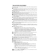
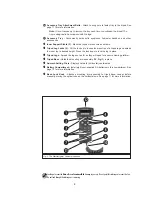
Packing List

Getting the telescope ready for first observations requires only a few minutes. When first
opening the packing box, note carefully the parts listed on your giftbox.

How to Assemble Your Telescope

The telescope attaches directly to the tripod. The telescope in this way is mounted in an
“Altazimuth” (“Altitude-Azimuth,” or “vertical-horizontal”) format. The telescope in this configuration
moves up and down and from side to side.

1.

Open the tripod: After removing the field tripod from its shipping carton, stand the tripod
vertically, with the tripod feet down and with the tripod still fully collapsed. Gently pull the
legs apart to a fully open position.

2.

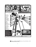
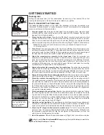
Attach the tray to the tripod: Place the tray (19, Fig. 1) over the inner support strut that
contains two bolt holes. Line up the bolt holes on the tray with the bolt holes on the strut.
Slide the two included bolts through the top of bolt holes (18, Fig. 1) and tighten the bolts
with the included wing nuts on the bottom side of the tray (Fig. 3). Tighten to a firm feel only.

Note: The tray does not have to be removed when you collapse the tripod at the end
of a viewing session.

3.

Three Pads: There are three pads in the tripod base (23, Fig. 1) and three pads on the
mounting arm assembly (16, Fig. 1). These pads allow the mounting arm assembly to move
more easily inside the base. See Fig. 4. This is pointed out just for the user's knowledge of
the telescope; the user does not need to adjust the pads which are pre-installed.

4.

Attach the mounting arm assembly to the tripod base: Place the mounting arm
assembly into the tripod base and continue to hold onto the arm assembly. With your other
hand, reach underneath the base and thread the mounting lock knob (26, Fig. 1) through
the tripod base and into the mounting arm assembly. Tighten to a firm feel only; do not
overtighten. While observing, you may wish to loosen this knob and rotate the mounting
arm assembly and optical tube on the horizontal axis.

5.

Remove the optical tube assembly from the cradle rings: The optical tube assembly is
shipped with the cradle rings attached. The rings need to be removed before they can be
attached to the mounting arm. Loosen the cradle lock knob (14, Fig. 1) until you can open
the cradle rings. Remove the optical tube assembly (13, Fig. 1) from the cradle rings.

6.

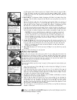
Remove 4 screws from the mounting arm shaft: Locate the four screws on the mounting
shaft. Remove the screws using a "+" (Phillips head) screwdriver. Set the screws aside.

7.

Attach the cradle to the mounting arm: Line up the cradle with the mounting arm shaft.
The cradle contains a molded "key" that fits into a slot on the shaft. Line up the key and the
slot, and slide the cradle onto the shaft. This automatically lines up the mating threads on
the cradle with the ones on the shaft. Replace the four screws into the mating threads using
the Phillips head screwdriver (Fig. 6). The key and slot on the shaft set limit stops for the
telescope so that it doesn't strike the base or pass beyond approximately 90° upright when
you use the Audiostar handbox.

8.

Attach and balance the optical tube: Replace the optical tube into the cradle ring. Tighten
the cradle ring lock knob so that it holds the optical tube loosely; do not tighten the cradle
ring lock knob at this point. Slide the tube back and forth until you find a position where the
tube remains horizontal (

i.e., without slightly tipping up or down). Tighten the cradle rings

lock knob to a firm feel. See Fig. 7. Adjust the length of the tripod legs to a comfortable
viewing height using the leg locks (21, Fig. 1).

9.

Attach the red dot viewfinder: The viewfinder has a slip-fit type bracket for easy attachment.
Just slide the viewfinder into the bracket until it clicks in place. To detach the bracket, press
down on the bracket's quick release tab and slide the bracket out. See Figs. 8a and 8b.

10. Attach the 90° diagonal prism (refractor models only): Pull out to remove the plastic

dust cover from the eyepiece holder. Slide the tube of the diagonal prism (3, Fig. 1e) into
the telescope’s eyepiece-holder (2, Fig. 1e) and tighten the thumbscrews (to a firm feel
only) to secure the diagonal prism in place.

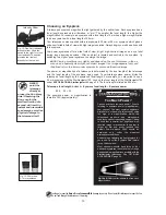
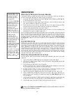
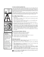
11. Insert the eyepiece: Remove the supplied eyepiece (3, Fig. 9) from its container and place

GETTING STARTED

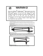
Looking at or near the 

Sun

will cause 

irreversible

damage to your eye. Do not point this telescope at or near the Sun.

Do not look through the telescope as it is moving.

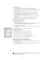
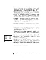
Fig. 6: Attach cradle to
mounting arm.

Fig. 8b: Press down on
the quick release tab to
detach the viewfinder
from the bracket.

Fig. 8a: Slide viewfinder
into slip-fit bracket.

Fig. 7: Attach and balance
the optical tube.

Summary of Contents for starnavigator ng series

Page 1: ...Instruction Manual StarNavigator Series Reflecting and Refracting Telescopes with Audiostar MEADE COM...

Page 2: ...of the image In the refracting telescope light is collected by a 2 element objective lens and brought to focus at F In contrast the reflecting telescope uses a concave mirror for this purpose F Eyepie...

Page 3: ...Appendix C Observing Satellites 40 Appendix D Training the Drive 41 Appendix E Replacing the Batteries 42 Appendix F Manually Setting Time and Date 42 Basic Astronomy 43 Meade Limited Warranty Back C...

Page 4: ...to a firm feel 4 Remove 4 screws from the mounting arm shaft Locate the four screws on the mounting shaft Remove the screws using a Phillips head screwdriver 5 Attach the cradle to the mounting arm L...

Page 5: ...drive base Remove the battery holder from the compartment and carefully lift the 9v connector out from the compartment Whenever you replace the batteries to safeguard the wires disconnect the 9v conn...

Page 6: ...1 23 24 25 E F Fig 1b Inset E Altitude setting circle F Altitude lock Fig 1d Inset Compass bubble level Fig 1e Inset Focus assembly and viewfinder 4 4 26 17 1 Focus Knob 2 Eyepiece Holder 3 90 Diagona...

Page 7: ...h D Auxiliary port A B C D 8 6 12 14 19 18 21 23 24 E F Fig 1b Inset E Altitude setting circle F Altitude lock 4 17 17 20 not visible opposite side 5 4 1 2 Fig 1e Inset Focus assembly 6 10 ASSEMBLYVIE...

Page 8: ...This page folds out...
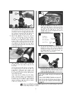
Page 9: ...h Bubble level can be used to level the optical tube when setting the Home Position included with refractng models only Altitude Setting Circle and Lock A Altitude Setting Circle Displays Altitude ver...

Page 10: ...sories 2 Inner Support Struts 3 Make the tripod more secure and stable 2 Tripod Leg Locks 3 Lift the lock up to loosen inner section of a tripod leg and extend the inner leg to desired height Press th...

Page 11: ...option or information about an object or subject depending on which function is being performed c ENTER Key Accesses in a sequential manner the next menu or data level in the Audiostar database See M...

Page 12: ...lp provides on screen information on how to accomplish whatever task is currently active Hold down the key and then follow the prompts on the display to access details of Audiostar functions in the He...

Page 13: ...n open the cradle rings Remove the optical tube assembly 13 Fig 1 from the cradle rings 6 Remove 4 screws from the mounting arm shaft Locate the four screws on the mounting shaft Remove the screws usi...

Page 14: ...ove the dust cover Pull out the dust cover 12 Fig 1 from the optical tube assembly 13 Fig 1 Assembly of the basic telescope is now complete The Red Dot Viewfinder Because the main telescope has a fair...

Page 15: ...ed as 800 mm Telescope focal length divided by Eyepiece focal length Eyepiece power 800 25 32 The eyepiece power or magnification is therefore 32X approximately NEVER point the telescope directly at o...

Page 16: ...er quality image If the image is fuzzy or ill defined reduce to a lower power eyepiece where the heat waves do not have such an effect on image quality Observing in early morning hours before the grou...

Page 17: ...t an object go to the Object menu See page 22 for instructions on navigating the Objects menu Once an object is selected on the AudioStar an audio presentation for that object will begin to play While...

Page 18: ...North Note Irregularities in the earth s magnetic field results in the direction of True North and Magnetic North differing and will vary from location to location To find True North use the bubble le...

Page 19: ...keys to cycle through the database of models Press ENTER when your model number displays 9 System initialization is complete In order to automatically locate and track celestial objects the telescope...

Page 20: ...message perform this procedure again NOTE Audiostar locates alignment stars based on the date time and location entered The alignment stars may change from night to night All that is required is for...

Page 21: ...the Scroll Down key until Solar System Saturn displays 4 Press ENTER Calculating displays and Astronomer Inside audio begins to play for the selected object On the AudioStar display Saturn displays an...

Page 22: ...m is reached Once in the Select Item level press MODE to return to the topmost level Select Item Object Audiostar Navigation Exercise To demonstrate how the Audiostar menu structure works the followin...

Page 23: ...MODE again to move up another level This is the top level Select Item 9 Press MODE again to return to the starting point of Select Item Object Entering data into Audiostar To enter numbers and text a...

Page 24: ...order out from the Sun followed by the Moon asteroids and comets Constellation is a database of all 88 Northern and Southern Hemisphere constellations When this menu option is chosen and a constellat...

Page 25: ...te into the Setup Date menu See DATE page 25 Moonrise and Moonset calculate the time that the Moon rises or sets on the current date Find rise and set times for other dates by entering a new date into...

Page 26: ...ER Start Stop Activates the alarm set previously Use the Scroll keys to toggle between ON and OFF When ON is displayed press ENTER to activate the alarm When the alarm time arrives Audiostar beeps Pre...

Page 27: ...wound around the assembly and tangled as the telescope slews to objects Off is the default setting Setup Menu The Setup menu s primary function is to align the telescope see EASY ALIGN page 17 However...

Page 28: ...s Reverse L R Reverses the functions of the Left and Right Arrow keys i e the Right key moves the telescope to the left Reverse UP DOWN Reverses the functions of the Up and Down Arrow keys i e the Up...

Page 29: ...tar including Characters Free Shows how much room is available in user defined object memory Version Shows the current version of the Audiostar software Reset Completely resets Audiostar Most values e...

Page 30: ...f sites When the desired site displays press ENTER To Edit a Site In this procedure you will enter a location that is not available in the Audiostar database by editing data of a nearby site You will...

Page 31: ...lays Press ENTER Object Solar System displays 5 Press the Scroll Up key twice and Object Landmarks displays Press ENTER Landmark Select displays 6 Press the Scroll Down key once Landmark Add displays...

Page 32: ...ntre the object you wish to have identified in the telescope s eyepiece 2 Navigate to the Object Identify option and press ENTER 3 Searching displays When Audiostar finishes calculating the name of th...

Page 33: ...bout the object Press MODE and Start Search Next displays again Press ENTER and the next item matching the parametres displays Repeat this procedure to display all the objects 8 Press MODE repeatedly...

Page 34: ...lays more than 15 000 celestial wonders galaxies nebulae star clusters stars and planets on your PC enabling even the beginner to locate and identify objects to observe with the telescope or to print...

Page 35: ...uitry f Do not leave the telescope inside a sealed car on a warm summer day excessive ambient temperatures can damage the telescope s internal lubrication and electronic circuitry Collimation StarNavi...

Page 36: ...4 Fig 29 appear off centre then the primary mirror tilt requires adjusting using the Phillips head screws of the primary mirror cell 3 Fig 25 These primary mirror tilt screws are located behind the p...

Page 37: ...cause irreversible damage to your eye Do not point this telescope at or near the Sun Do not look through the telescope as it is moving 2 1 3 3 2 1 2 3 4 5 1 2 1 2 3 2 1 2 3 4 3 6 2 5 1 4 Fig 23 Fig 24...

Page 38: ...gnment Altazimuth Slew speeds 1x sidereal to 5 5 sec in 9 increments Tripod Aluminum full length adjustable w accessory tray Optical tube dimensions 3 25 8 3 cm x 34 86 4 cm Batteries user supplied 8...

Page 39: ...sec in 9 increments Tripod Aluminum full length adjustable w accessory tray Optical tube dimensions 5 5 5 5 cm x 18 45 7 cm Batteries user supplied 8 x AA Hand controller AudioStar StarNavigator130 Op...

Page 40: ...how Earth s time zones are determined by longitude lines The zero line was arbitrarily chosen to pass through the constellation Pegasus a sort of cosmic Greenwich meridian R A coordinates range from 0...

Page 41: ...0 displays Use the Number keys to enter the digits for the Right Ascension coordinate of your object When you are finished press ENTER 7 Declination 00 00 displays Use the Number keys to enter the di...

Page 42: ...escope then continue with this procedure 9 With about 20 seconds left on the countdown timer start watching through the telescope viewfinder for the satellite to enter the field of view 10 When the sa...

Page 43: ...might find helpful Topics 1 How is a star born How does a solar system form 2 How is the distance to a star measured What is a light year What is red shift and blue shift 3 How are the craters on our...

Page 44: ...ss the Right Arrow key to move to the next position 9 2 is now highlighted The date display now reads 06 MAR 2003 Press the Right Arrow key three times until the 3 is highlighted 10 Press the Number k...

Page 45: ...made of glass and metal but something far more a window through which the beating heart of the universe might be observed Audiostar Glossary Be sure to make use of Audiostar s Glossary feature The Gl...

Page 46: ...Saturn had ears Saturn s rings are composed of billions of ice particles ranging in size from a speck of dust to the size of a house The major division in Saturn s rings called the Cassini Division is...

Page 47: ...the product testifies to its conformity Date of CE Marking April 12 2010 Steve Murdock President Meade Instruments Corp RECYCLING INFORMATION EU Countries only Correct Disposal of this Product Waste...

Page 48: ...mal wear and tear Meade specifically disclaims special indirect or consequential damages or lost profit which may result from a breach of this warranty Any implied warranties which cannot be disclaime...

Reviews: