Technisches
Manual
Weather
station
SCN
‐
WS3HW.01
MDT technologies GmbH •
51766 Engelskirchen • Papiermühle 1
Tel.: +49-2263-880 • Fax: +49-2263-4588 • [email protected] • www.mdt.de
24
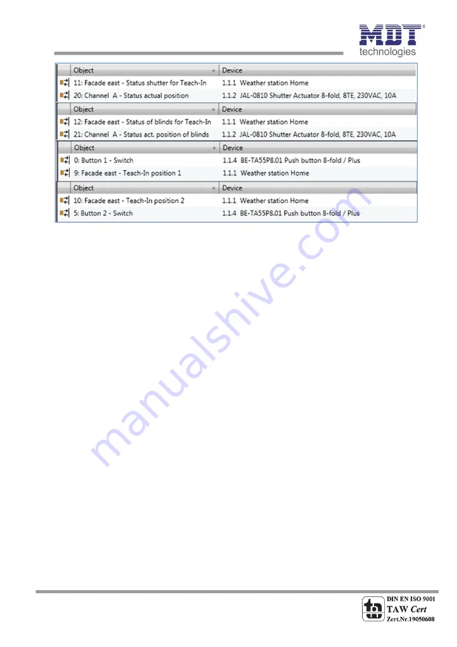
Illustration
11:
Programming
Teach
‐
In
function
The
illustration
shows
the
fragmentation
of
the
Teach
‐
In
objects
into
four
different
group
addresses.
The
state
objects
for
the
Teach
‐
In
function
are
connected
with
the
state
objects
of
the
channel,
which
is
to
be
controlled,
of
the
shutter
actuator.
At
this
example,
the
1
bit
activation
objects,
Teach
‐
In
position
1
&
2,
are
connected
with
a
push
‐
Button.
It
is
also
possible
to
connect
them
with
a
display
or
anything
else.
As
soon
as
the
push
‐
button
sends
a
logical
“1”,
e.g.
the
button
1
to
the
Teach
‐
In
position
1,
the
weather
station
reads
the
current
position
of
the
shutter
actuator
from
the
state
objects
and
overwrites
the
values
for
the
facade
controlling
with
these
values.
At
a
new
activation
of
the
facade
control,
the
weather
station
sends
the
new
values
and
the
shutter/slats
drive
to
this
position.
There
is
an
additional
parameter
at
the
general
settings,
have
a
look
at
page
10,
which
defines
whether
the
Teach
‐
In
values
shall
be
kept
after
a
new
programming
or
the
weather
station
shall
overwrite
them
with
the
parameterized
one.
Temperature
‐
/Blockfunction
The
facade
control
can
also
be
parameterized
with
the
influence
of
temperature.
This
enables
that
the
facade
control
gets
only
active
if
the
temperature
is
higher
than
a
certain
value.
The
temperature
can
be
read
from
the
internal
temperature
sensor
or
from
any
external.
An
additional
communication
object
appears
if
the
weather
station
shall
receive
an
external
temperature.
The
connection
to
the
internal
sensor
occurs
automatically
if
activated.
By
activation
this
function,
the
faced
control
is
only
active
above
the
parameterized
temperature.
If
the
temperature
falls
below
the
adjusted
function,
the
facade
control
is
deactivated.
The
blocking
object
for
the
facade
control
allows
blocking
the
facade
control
with
a
logical
“1”.
The
following
chart
shows
the
relevant
communication
objects:


