C O N D E N S E R - WATER PIPING
General
_.-
For the best performance, the condenser water inlet
is established as the bottom connection of the con-
denser.
Water cooled condensers may be piped for well
water applications, or for use in conjunction with a
cooling tower. Cooling tower applications should in-
clude a small amount of waste circulating water to
prevent building up of solids in the tower basin.
Head Pressure Control
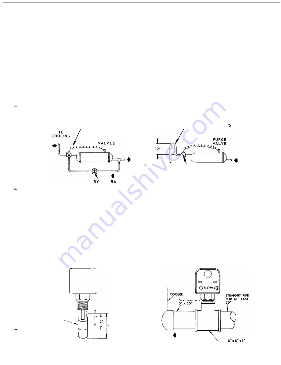
Some means of controlling operating head pressure
must be provided. A three way pressure actuated water
regulating valve is recommended for cooling tower ap-
plication, as indicated in Figure 8. This arrange-
ment wi II maintain a constant condensing pressure, re-
gardless of temperature conditions and assures enough
head pressure for proper thermal expansion valve op-
eration. Full water flow is assured to the tower with
this arrangement.
Well Water
Where well water is used for condensing refrigerant, a
direct acting water regulating valve is recommended-
See Figure 9. The valve is n orma I ly installed at
the outlet of the condenser. On shut down, the valve
will close and, in this way, prevents water siphoning
out of the condenser. Siphoning causes drying of the
water side of the condenser and rapid buildup of foul-
ing. When no valve is used, a loop at the outlet end
is recommended - See Figure 9.
WATER REGULATING VALVES (EACH CONDENSER)
FIGURE NO. 8
3 WAY WATER
REGULATING VALVES
TOWER
PURGE
MAIN
CONDENSER
WATER SUPPLY
FROM PUMP
PASS
LANCING
VALVES OR COCKS
FIGURE NO. 9
LOOP REQUIRED WHEN NO
REGULATING VALVE USED
,
l
TO DRAIN
\
FROM MAIN
CONDENSER
PUMP
DIRECT ACTING WATER
REGULATING VALVE
COOLING TOWER SYSTEM
WELL WATER COOLING SYSTEM
WATER FLOW SAFETY SWITCH (OPTIONAL)
A water flow safety switch is available as optional
equipment for all Type WHR chillers. The flow switch
must
be
field
installed and wired into the SEASONPAK
water chiller control center as indicated on the draw-
ings.
The flow switch should be installed in a horizontal
run in either the supply or return chilled water piping
as follows:
1. Apply pipe sealing compound to only the threads of
the switch and screw unit into D’ x D’ x 1” reducing
tee(See Figure 10). The flow arrow must be pointed
FIGURE NO. 10
FLOW SWITCH
PADDLE
FLOW SWITCH
in the correct direction.
2. Piping should provide for a straight length before
and after the flow switch of at least 5 times the
pipe diameter.
CAUTION: Make sure the arrow on the side of the
switch is pointed in the proper direction of flow.
The flow switch is designed to handle the control
voltage and shouldonly be connected according to the
wiring diagram (See Wiring Diagram inside control
box door).
PIPE SECTION
FLOW DIRECTION
T E E
VIEW FROM END OF COOLER
Page 7


