gizing a 220 volt heater.
This causes the normally
closed bi-metallic relay switch of this control to open
after a delay of approximately 90 seconds or less,
stopping the compressor and closing the liquid line
solenoid valve. The time delay prevents nuisance trip
out on momentary low suction pressure and permits the
operation of the system on a “pumpdown cycle”.
The control must be checked while the system is
operating. To check the control, install a volt meter
or 220 volt light across terminal T1 and T2 of the low
pressure freeze control. There should be a voltage
indication or the test light will glow indicating the
contacts are opened. Throw the pumpdown switch to
the manual position and check the pressure at which
the test light goes out or the volt meter goes to zero.
In actual operation, the compressor wi II shut down and
the safety light will go out. The control can be man-
ually reset in about 2 minutes.
Thermostat - The thermostots supplied on all pack-
aged chillers are factory calibrated for use in the re-
turn water line to the cooler inlet. The thermostat
bulb is installed in a well in the return water line in
order to be more stable under temperature changes due
to load conditions. The return water does not change
temperature as rapidly as the outlet because of the
“fly whee I effect” of the total water system. This re-
sults in stable control of the outlet water temperature.
Normally the thermostat requires no adjustment in the
field other than the dial setting for the required con-
trol point.The control is preset at the factory to main-
tain a 44F average leaving water temperature through-
out the loading and unloading sequence of the unit,
based on a full load cooling range of 10F. It should
be realized, however, that there will be a fluctuation
in the leaving,water temperature as the unit cycles,
unloads and loads.
On a two stage thermostat, the dial setting indi-
cates the average leaving water temperature that the
control will maintain.At a 44F setting, the high stage
should actuate at approximately 51F return water and
41F leaving based on 10F. cooling range. The low
stage will open at 46F return or 41 F leaving (5F TD
or 50% capacity). As the water warms up, the low
stage should cut in at approximately 49F which is the
inlet and outlet temperature with the unit off and the
high stage should operate at 54F return or 49F leaving.
These settings may be checked by operating the
unit and slowly regulating the load from full to mini-
mum and return. It may then be necessary to adjust the
dial and/or differential between switches to obtain
these values.
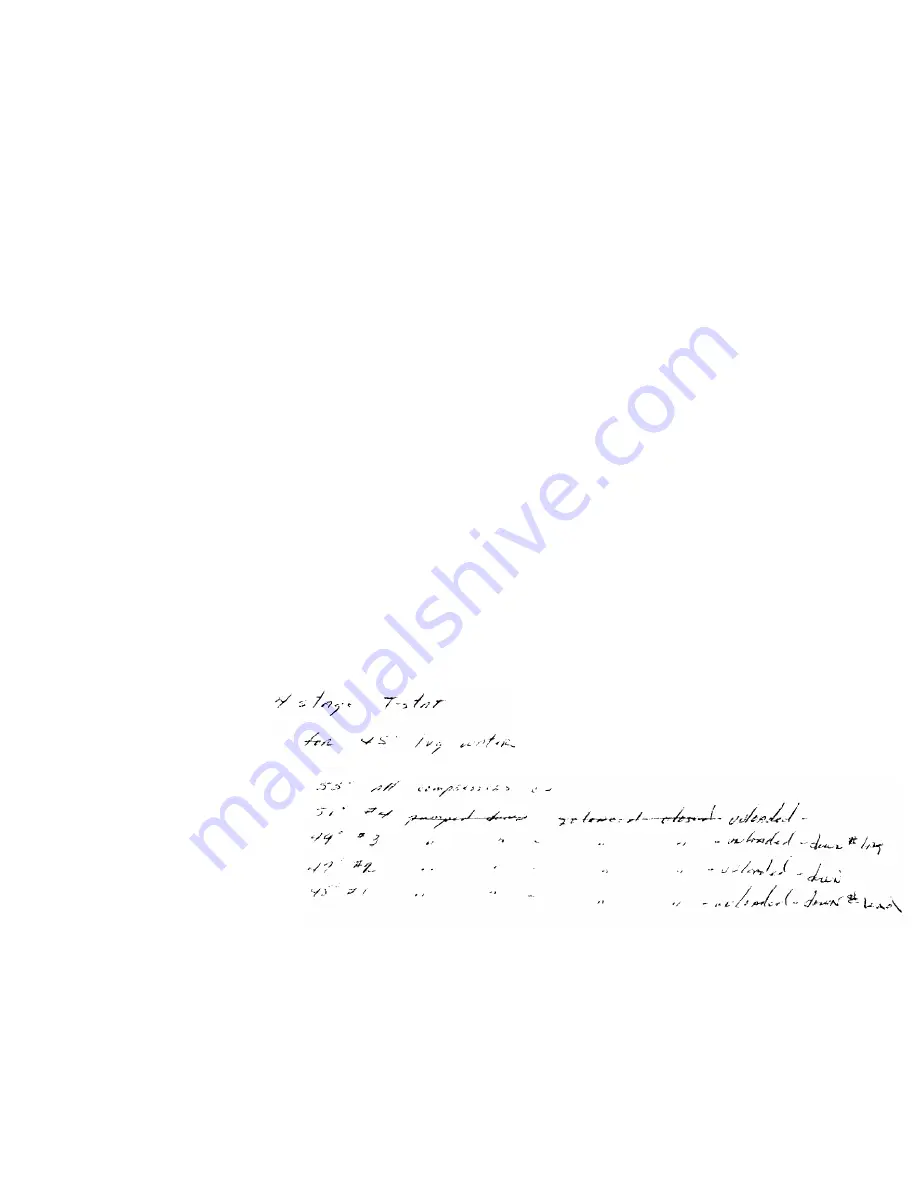
On a four stage thermostat, the dial setting indi-
cates the cut out point of the low stage switch which
represents the average leaving water temperature de-
sired. The high stage or #4 switch should be actuated
at approximately 51F return water temperature, #3 at
49F, #2 at 47F and #1 at 45F which is the dial setting.
The cut in point will be approximately 2F higher than
the cut out on each switch.
These settings may be checked by operating the
unit and slowly reducing the load. The four stage
thermostat has a fixed switch differential and fixed
differential between switches. DO NOT make any ad-
justments other than the dial as this is a preset pre-
cision control.
CAUTION: Response time on thermostat is slow, con-
sequently, approximately 5 minutes must be allowed
for bulb response (after attaining system steady-state
operotion) before any or each adjustment to thermo-
stat is made.
Page 25


