background image

TECHNICAL NOTE – OPERATION OF MT4000 TWTA  

10/24/03 


TN4000-3 

MCL, INC. 

20 of 46 

3.2.12 Coupling Factor Parameter Edit Screen 


This screen is accessed from the coupling factor edit line screen. The screen shown at bottom of 
the figure above is a typical EDIT screen for coupling factor parameters. While one of these 
screens are displayed the operator can use the adjustment knob to change the parameter shown on 
the fourth line. The adjusted value will take effect once the accept buttons is pressed. The third 
line is the value of the parameter before it is adjusted. If the operator were to press the menu 
select button from this screen the coupling factor edit line screen would be displayed again. 
These coupling factor parameters can be adjusted from only the Local panel. 


3.2.13  Communications Set Up Screen 


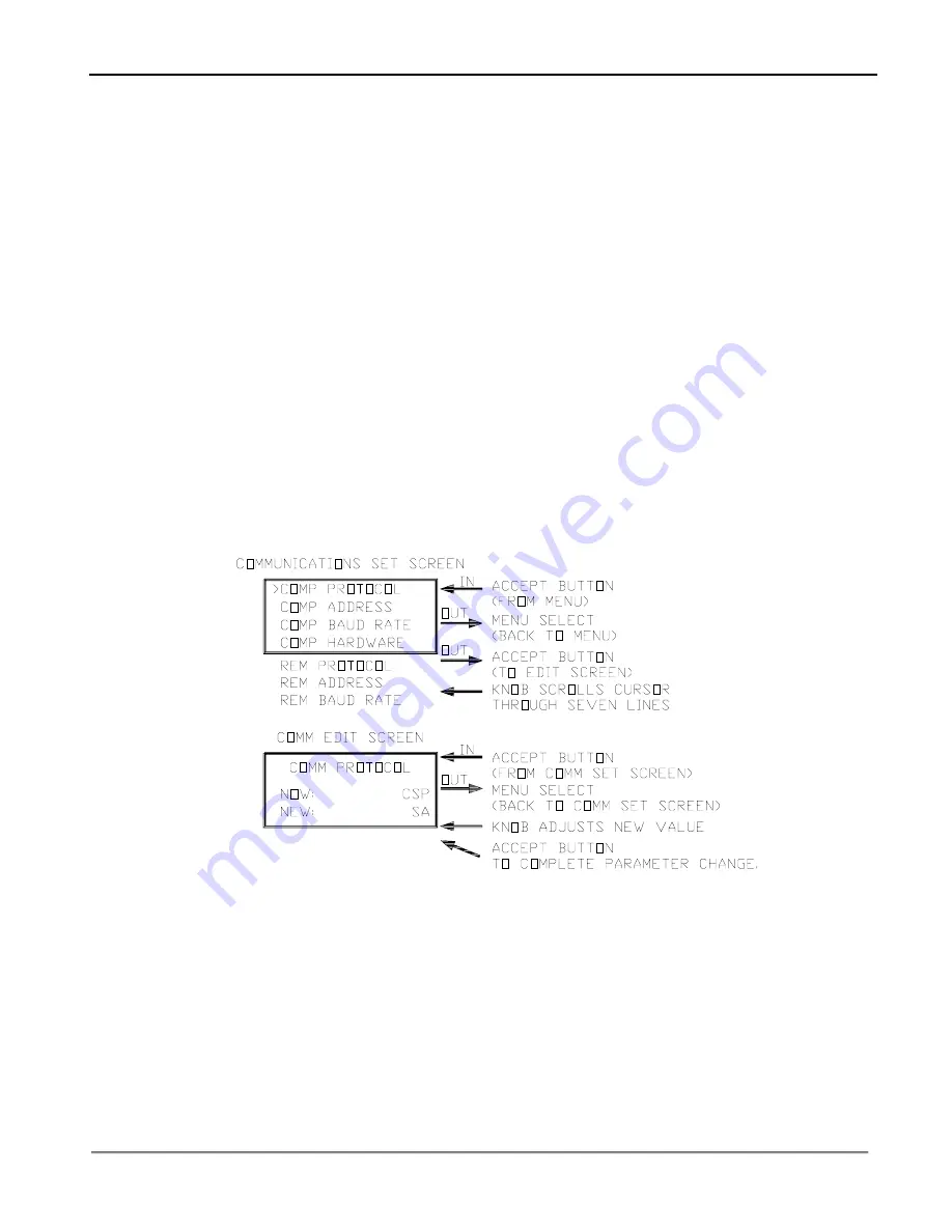
This screen will display the configuration for both the remote and computer interfaces. This 
screen is accessed from the menu screen. When the screen shown at the top of the figure below is 
displayed the operator can select which parameter to modify from those listed on this menu. 
Notice there are seven menu parameters to select from, but the screen can only display four at a 
time. By rotating the knob CW these selections will scroll up one at a time, and CCW down one 
at a time. Once the cursor is pointing at the desired selection the operator will press the Accept 
button. This will cause the edit screen for the selected parameter to be displayed.  If the operator 
were to press the menu select button from this screen the menu screen would be displayed again. 


3.2.14  Communications Parameter Edit Screen 


This screen is accessed from the communications set up screen. The screen shown in the bottom 
of the figure above is a typical EDIT screen for Remote or Computer interface communications 
parameters. While one of these screens are displayed the operator can use the adjustment knob to 
change the parameter shown on the fourth line. The adjusted value will take effect once the 
accept buttons is pressed. The third line is the value of the parameter before it is adjusted. If the 
operator were to press the menu select button from this screen the communications set up screen 
would be displayed again. 


Summary of Contents for MT4000 TWTA

Page 1: ...TN4000 3 Technical Note Operation of MT4000 TWTA October 24 2003 Mark Schmeichel 10 24 03 Engineering Date...

Page 2: ...ent 13 4 0 HPA OPERATION 21 4 1 HPA Control Modes 21 4 2 HPA Operating Modes 24 4 3 RF On Off Control 25 4 4 Faults Alarms 26 4 5 HPA Gain Control 29 4 6 Diagnostic Interface 31 4 7 Optional Local Int...

Page 3: ...WTA 10 24 03 TN4000 3 MCL INC 3 of 46 LIST OF APPENDICES Appendix A 40A1546 CSP Protocol Specification Appendix B 40A1715 SA Bus Compatible Protocol Specification Appendix C 46A0204 CSP Command Set Ap...

Page 4: ...s the WARNING or CAUTION is repeated throughout the text Prior to starting any task THE WARNINGS or CAUTIONS included in the text for that task should be reviewed and understood An operating or mainte...

Page 5: ...tage supply turned on Under certain conditions dangerous potentials may exist when the power control is in the off position due to charges retained by capacitors To avoid injuries always remove power...

Page 6: ...inside the unit Do not insert objects through air intake screen on rear of drawer When testing always ground the drawer chassis RF RADIATION Exposure to RF radiation may cause serious bodily injury p...

Page 7: ...es can produce dangerous possibly fatal X Rays HOT SURFACES Surface temperature of tubes and other air cooled ports can reach several hundred degrees centigrade RF OVERDRIVE The unit may be damaged by...

Page 8: ...d and selected for high reliability and maximum use of existing designs Mechanical and electrical safeguards are utilized throughout the system to insure safety of operating personnel 3 0 CONTROLS IND...

Page 9: ...e HPA is in the Transmit state the HPA will switch to the Standby state the Yellow LED in the button will be continuously illuminated 3 1 4 Transmit Button LED While no faults are present if this butt...

Page 10: ...data transmitted to the remote port 3 1 13 RF High LED The Yellow LED will illuminate when the detected forward power exceeds the user specified level 3 1 14 RF Low LED The Yellow LED will illuminate...

Page 11: ...de the button is illuminated the amplifier is switched to the antenna port of the RF switch 3 1 21 Load Button LED When this button is activated though the 1 1 switchover this HPA will be put into the...

Page 12: ...T4000 TWTA 10 24 03 TN4000 3 MCL INC 12 of 46 3 1 25 Accept Button This button will be used to select adjustable parameter on any screen 3 1 26 Menu Select Button This button is used to move between d...

Page 13: ...4 03 TN4000 3 MCL INC 13 of 46 3 2 Front Panel Display Screen Content This figure shows an overview of the TWTA screens and the flow between these screens The following paragraphs describe each screen...

Page 14: ...ent delay the first line of the normal operating screen will display the remaining filament delay time After filament delay time ends the RF forward power value will be displayed on the first line of...

Page 15: ...l press the Accept button which will cause the selected screen to be displayed If the operator were to press the menu select button from this screen the normal screen would be displayed again 3 2 5 Ga...

Page 16: ...yed If the operator were to press the menu select button from this screen the menu screen would be displayed again 3 2 7 Adjustment Edit Screen These screens are accessed from the adjustment menu scre...

Page 17: ...table trip levels are exceeded causing an event entry the level that was exceeded will also be stored in the log and presented on the fourth line of the display The time resolution of the log will be...

Page 18: ...Uncalibrated RF Forward Uncalibrated RF Reflected Uncalibrated Tube Drive Uncalibrated OPERATING STATES End of Log Standby Local RF Off Local RF On Transmit Remote RF Off Remote RF On Local Override O...

Page 19: ...one at a time Once the cursor is pointing at the desired selection the operator will press the Accept button This will cause the edit screen for the selected line to be displayed see the next paragrap...

Page 20: ...the operator can select which parameter to modify from those listed on this menu Notice there are seven menu parameters to select from but the screen can only display four at a time By rotating the kn...

Page 21: ...se control modes are mutually exclusive the operational states of the MT4000 at any one time These interfaces are the Local panel Remote Interface J4 and Computer Interface J5 4 1 1 Local Control Whil...

Page 22: ...ces 4 1 3 Computer Control 4 1 3 1 Control Priority While the HPA is in the Computer mode the operator at the Computer device will be allowed to control the HPA While in the Computer mode the Local pa...

Page 23: ...40A1546 or SABUS 46A0203 40A1715 COMP ADDRESS Hexadecimal 01 01 through 7F CSP 31 through 7E SA7670 COMP BAUD RATE 9600 1200 2400 3600 4800 9600 14400 19200 or 28800 COMP HARDWARE RS485 RS485 or RS23...

Page 24: ...OFF OFF OFF ON STANDBY OFF OFF ON OFF OFF OFF AFTER FILAMENT DELAY WITH A FAULT OFF OFF OFF OFF OFF ON TRANSMIT OFF OFF OFF OFF ON OFF DURING FAULT COUNTER CYCLE WITH TRANSMIT IMMINENT OFF OFF OFF ON...

Page 25: ...as a power failure and then the HPA power returns After the power failure Transmit selected will be activated during filament delay if no faults are present during delay Second while the HPA is in the...

Page 26: ...larm Alarms WILL NOT affect the operating state of the HPA All alarms are self clearing and do not require a Fault Reset except RF Switch Failed alarm which will latch until the Reset button is presse...

Page 27: ...forced off Standby Transmit are disabled FAULTS Tube Temp Switch Chassis Interlock RF Reflected Tube Overdrive Helix Surge User Interlock W G Arc HV Over Volt Filament Under Current Tube Temp Analog...

Page 28: ...Tube Drive Power meter 4 4 6 Tube Fault Counter Operation If the MT4000 is to be left in an unattended earth station or during a degassing operation or if the tube is nearing the end of it s life the...

Page 29: ...nt All of these methods of adjust depend on the operator watching an indication of the HPA output power while making the adjustment Since the attenuator is in the input side of the HPA there is not a...

Page 30: ...nditions occur The set Auto Power level exceeds the top Forward Power calibration point If the TWTA drops out of Transmit If a Disable Auto Power command is received while the TWTA is in the Computer...

Page 31: ...ding and uploading data to the HPA The diagnostic interface program has information built into the Help menu to give the operator additional assistance The Windows cut paste functions are enabled on a...

Page 32: ...ace program click on the Settings tab see the figure below 2 Click on the Download All Settings button to refresh the settings display 3 To save the data to disc once the status is done downloading cl...

Page 33: ...g traffic or an interruption in service may occur The HPA must be in a maintenance mode to upload settings or an interruption of service may occur 2 On the Diagnostic Interface program click on the Se...

Page 34: ...hat menu then on the Save menu select Event Log The diagnostic program will automatically produce a file name which includes the HPA serial number events and today s date 4 The add to database box whe...

Page 35: ...ation The diagnostic program will automatically produce a file name that includes the HPA serial number cal tables and today s date 4 6 6 Downloading the Data Log 1 On the Diagnostic Interface program...

Page 36: ...data select the HPA from the drop down list on the left side and then select the parameter to graph from the list on the right side There is no timescale Data points are equally spaced across the bot...

Page 37: ...TECHNICAL NOTE OPERATION OF MT4000 TWTA 10 24 03 TN4000 3 MCL INC 37 of 46...

Page 38: ...however no control inputs will be accepted from the membrane panel As long as the local panel microprocessor did not fail the diagnostic computer and remote interfaces will be able to provide status b...

Page 39: ...eset Phase Voltage can be found in the MT4000 test data which was supplied with the unit The linearizer Mag control is set for the specific TWT characteristics and should not be moved from the factory...

Page 40: ...ce J6 User interface J6 is supplied to allow various earth station equipment such as exciters to be wired into the MT4000 Refer to TN4000 2 Technical Note Installation Guide for MT4000 paragraph Conne...

Page 41: ...NC 41 of 46 4 11 2 Procedure to Limit RF Input to the HPA 1 Rated Power No Attenuation With the HPA attenuation at minimum measure the amount of power required to drive the MT4000 system to rated powe...

Page 42: ...igh voltage power supply will both be turned off until the RF drive level is backed down To change the Tube Overdrive Fault level from the factory set level may result in degradation or permanent dama...

Page 43: ...ser Interface J6 and Switchover Interface J7 are not used the supplied cheater plugs should be installed on the rear panel 11 Connect the Remote Panel Computer Interface cables to the rear panel 5 2 O...

Page 44: ...When the above check list has been completed and the caution list is reviewed the system is ready for activation To activate the system the following steps should be followed 1 Activate the HPA Main P...

Page 45: ...r the rated output power to be expected from the amplifier system while staying within the TWT current and voltage limitations Monitor the output reflected RF power to insure that the transmission lin...

Page 46: ...Customer Service Guide for MT4000 6 0 SHUT DOWN PROCEDURE To discontinue operation of a MT4000 TWT amplifier system the following procedure is recommended for system shutdown 1 Remove the input RF dri...

Page 47: ...N OF MT4000 TWTA 10 24 03 TN4000 3 MCL INC A APPENDIX A 40A1546 CSP Protocol Specification APPENDIX B 40A1715 SA Bus Compatible Protocol Specification APPENDIX C 46A0204 CSP Command Set APPENDIX D 46A...

Reviews: