background image

6

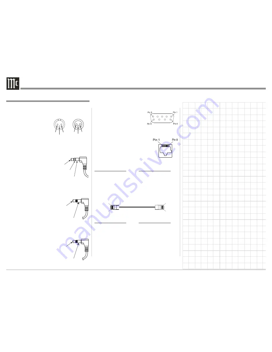
RS232 DB9 Connector Pin Layout

1. N/C 

6. N/C

2. Data Out (TXD)  7. N/C

3. Data In (RXD) 

8. N/C

4. N/C 

9. N/C

5. Gnd.

Ethernet RJ45 Socket

1. Tranceive Data (+) 

5. N/C

2. Tranceive Data (-) 

6. Receive Data (-)

3. Receive Data (+) 

7. N/C

4. N/C 

8. N/C

Ethernet Cable - Straight Thru Connections

Pin Number - Wire Color 

Pin Number - Wire Color


1. Orange/White 

→ 

1. Orange/White


2. Orange 

→ 

2. Orange


3. Green/White 

→ 

3. Green/White


4. Blue 

→ 

4. Blue


5. Blue/White 

→ 

5. Blue/White


6. Green 

→ 

6. Green


7. Brown/White 

→ 

7. Brown/White


8. Brown 

→ 

8. Brown

Ethernet Cable - Crossover Connections

Pin Number - Wire Color 

Pin Number - Wire Color


1. Orange/White 

→ 

1. Green/White


2. Orange 

→ 

2. Green


3. Green/White 

→ 

3. Orange/White


4. Blue 

→ 

4. Blue


5. Blue/White 

→ 

5. Blue/White


6. Green 

→ 

6. Orange


7. Brown/White 

→ 

7. Brown/White


8. Brown 

→ 

8. Brown

XLR Connectors

Below is the Pin configuration for the XLR Balanced 

Output Connectors on the MX121. Refer to the dia-

grams for connections:

  PIN 1: Shield/Ground

  PIN 2: + Signal

  PIN 3: - Signal

PWR CTRL (Power Control)/Trigger Connectors

The MX121 Power Control Out/ Trigger Output Jacks 

send an On/Off signal from 0 to +12 volts with a total 

current up to 50mA when 

connected to other Com-

ponents. A 1/8 inch stereo 

mini phone plug is used for 

connection to the Power 

Control/ Trigger Outputs on 

the MX121.

Data In and Output

The MX121 Data In receives 

Remote Control Signals from 

Source Components. The 

MX121 Data Out sends Remote 

Control Signals to McIntosh 

Source Components. A 1/8 inch 

mini phone plug is used for connection.

IR In Port Connector

The IR IN Port also uses a 1/8 

inch mini phone plug and al-

lows the connection of external 

IR Receivers to the MX121.

Connector and Cable Information

PIN 1

PIN 2

PIN 3 

Connector and Cable Information

Pin 1

Pin 8

Pin 1

Pin 8

PIN 2 

PIN 1 

PIN 3 

Input

Output

Data

Signal

Ground

IR Data

Control

Ground

+

12V DC

(Trigger

Control)

Ground

N/C

Summary of Contents for MX121

Page 1: ...McIntosh Laboratory Inc 2 Chambers Street Binghamton New York 13903 2699 Phone 607 723 3512 www mcintoshlabs com MX121 A V Control Center Owner s Manual...

Page 2: ...r replacement of the obsolete outlet 10 Protect the power cord from being walked on or pinched particularly at plugs convenience receptacles and the point where they exit from the apparatus 11 Only us...

Page 3: ...DMP Digital Media Player DLNA Certified Product Function FINDS PLAYS Content Type audio images videos Check supported media formats DLNA consumer website www dlna org Some content may not be compatib...

Page 4: ...or you to record that information Serial Number ________________________________ Purchase Date _ _______________________________ Dealer Name _ ________________________________ Table of Contents Safety...

Page 5: ...dio Video Output Signal for record ing purposes instead of an A V signal to a second room The Zone 3 allows for listening to a differ ent Audio Source from either the Main Zone or Zone 2 For more info...

Page 6: ...d Output Connectors on the MX121 Refer to the dia grams for connections PIN 1 Shield Ground PIN 2 Signal PIN 3 Signal PWR CTRL Power Control Trigger Connectors The MX121 Power Control Out Trigger Outp...

Page 7: ...unctions LED Channel Status Indicators The MX121 includes twenty five LEDs on the front panel to indicate what type of operating signals are being received signal processing mode and the output format...

Page 8: ...n for your MX121 Dimensions Front View of the MX121 Rear View of the MX121 17 1 2 44 5cm 7 5 8 19 4cm 7 1 8 18 1cm 6 3 8 16 2cm 13 1 4 33 7cm 17 1 8 43 5cm Side View of the MX121 16 1 2 41 9cm 3 16 0...

Page 9: ...ow at least 2 inches 5 08cm above the top and 2 inches 5 08cm on each side so airflow is not obstructed Allow 19 1 2 inches 49 53cm depth behind the front panel Allow 1 7 16 inch 3 66cm in front of th...

Page 10: ...he identification of Rear Panel Connections for the MX121 A V Control Center is located on a separate folded sheet contained in the Owner s Manual Packet Refer to separate sheet Mc1A for the Rear Pane...

Page 11: ...the Power Control Output Jack from the last component a Power Control Input connection was made onto the first Power Amplifier with a Power Control Input jack Data Control Connections 6 Connect a Con...

Page 12: ...rol Cable from Main Zone Power Amplifier Three Power Control Out to the Pow ered Subwoofer Power Control In Jack 5 Connect any additional McIntosh Components in a similar manner as outlined in steps 1...

Page 13: ...o the Satellite Analog Output Jacks Analog Video Connections 5 Connect Component Video Cables from the MX121 COMPONENT VIDEO IN 1 Jacks to the Audio Video Disc Player Component Video Out put Jacks mak...

Page 14: ...Controls and Push buttons The identification of the MX121 A V Control Cen ter Front Panel Display Controls and Push buttons is located on a separate folded sheet contained in the Owner s Manual Packe...

Page 15: ...h Buttons The identification of Remote Control Push Buttons for the MX121 A V Control Center is located on a separate folded sheet contained in the Owner s Manual Packet Refer to separate sheet Mc4A a...

Page 16: ...n Screen Menus please refer to the set of MX121 Menu separate folded sheets MX121 Menu 1 thru Menu 7 and to separate sheets Mc4A thru Mc4B for Push button identifications These separate sheets are con...

Page 17: ...s as Radio Frequency Interference RFI may cause measurement disruptions even if the cell phone is not in use 5 Do not unplug the setup microphone from the main unit until Audyssey Auto Setup is comple...

Page 18: ...Measure highlighted On Screen press the ENTER Push button to start the Mea surement Process A special audio test signal will be sent to all previously detected channels one at a time Refer to the illu...

Page 19: ...res ults To proceed press Next Select item to check Spkr Config Check Distance Check Ch Level Check Crossover Check Next Store AUTO SETUP AUDYSSEY AUTO SETUP ENTER Enter RETURN Cancel MultEQ XT 6 6 S...

Page 20: ...Y AUTO SETUP RETURN Cancel MultEQ XT There is too much noise in the room for accurate measurements to be made Speaker or subwoofer sound is too low for accurate measurements to be made Either turn off...

Page 21: ...ovider is also DHCP compliant no user manual settings in the MX121 need to be made for normal operations Network Manual Settings When the MX121 is connected to a network with no DHCP Functions the fol...

Page 22: ...Mask 255 255 255 000 Default gateway 000 000 000 000 Primary DNS 000 000 000 000 Secondary DNS 000 000 000 000 Exit Proxy ENTER Enter Figure 11 MANUAL SETUP NETWORK SETUP NETWORK CONNECTING Proxy serv...

Page 23: ...ther Setup Trigger Out 2 Use the Directional Push buttons to select Trigger 1 or Trigger 2 3 Then select either a given Zone a given Input Source or HDMI Output 1 or 2 to activated the previously sele...

Page 24: ...ed up the reassignment process make a list of the desired changes A blank reassignment chart has been provide on the MX121 Menu separate folded sheet Menu 7 for this purpose Notes 1 The PHONO TUNER an...

Page 25: ...t in Audyssey automatically performs all the necessary speaker settings and corrects for the undesirable room acoustic Refer to page 17 If for some reason you desire to manually enter all the speaker...

Page 26: ...e MX121 volume select MX121 Inputs etc Refer to the TV Owner s Manuals for details Standby Source The MX121 has a HDMI pass thru mode when the HDMI Control is set to ON and the TV HDMI Control is also...

Page 27: ...tivate the Front Panel Sensor when the external sensor is disconnected repeat steps 1 and 2 Figure 28 Picture Adjust Settings The MX121 provides standard video adjustments for Sources having Video Sig...

Page 28: ...deo Connections asigned to it the resolution of the HDMI connection can be set differently than the Component Video connection Vid eo Signals based on 50Hz can not be set to 1080p 24Hz Progressive Mod...

Page 29: ...ray players with 7 1 channel outputs If after performing the players internal setup and the Subwoofer Output is either too low or too high in level to match the other channels choose the MX121 other...

Page 30: ...AUDIO VIDEO ADJUST AUDIO ADJUST Surround Parameter Audyssey Settings Manual EQ Audio Delay Figure 35 Soften treble in movies for clearer sound AUDIO VIDEO ADJUST AUDIO ADJUST SURROUND PARAMETER HT EQ...

Page 31: ...31 Setup Mode con t...

Page 32: ...urce and is indicated on the top line of the Front Panel Informa tion Display Refer to figure 40 The selection of the sources may also be accomplished by pressing the appropriate push button twice on...

Page 33: ...L SIGNAL Display will illuminate when the audio input signal is Digital G The HDMI SIGNAL Display will illuminate when the audio input signal is Digital High Definition such as Dolby True HD or DTS Ma...

Page 34: ...cessing and PURE DIRECT bypasses all digital processing Note When switching between the three modes the sound is momentary muted Surround Mode Press the AUTO Push button to allow the MX121 processing...

Page 35: ...Remote Control various Audio Input Connection Op tions appear on the MX121 Front Panel Information Display Depending on the Input Souce Name and the connection assigment the choices could include Aut...

Page 36: ...rol are for selecting Source Inputs for the Main Zone only 2 The operation of Zone 3 is similar to Zone 2 except Zone 3 is Audio only How to Operate the MX121 con t Front L Front R Center Subwoofer Su...

Page 37: ...d room acoustics and activates MultEQ XT Dynamic Volume solves the problem of large vari ations in volume level between TV movies and other content between quiet passages and loud passages etc by auto...

Page 38: ...te mode press STATUS during play back to check the title name artist name and album name mixed at 10 dB below film reference 15dB Select this setting for pop rock music or other program material that...

Page 39: ...55 Figure 55 AirPlay icon 6 From the list appearing in iTunes select McIntosh MX121 Refer to figure 56 Streaming music from iPhone iPod touch or iPad To stream music stored on your iPhone iPod touch...

Page 40: ...Protocol standards can be played on the MX121 4 The MX121 is compatible with USB memory de vices in FAT16 or FAT32 format 5 The MX121 plays back image JPEG files in the orientation in which they are s...

Page 41: ...41 How to Operate the MX121 con t...

Page 42: ...bility store into Preset Local Stations 1 7 Internet Radio Search Stations Search Podcasts Recommended Stations radiomcintosh com Recently Played Search by Keyword Figure 72 Favorites 1 3 radiomcintos...

Page 43: ...Stations for quick recall To enter a Internet Radio Station perform the following steps 4 Press the MEMORY Push button Refer to figure 77 Then select Preset Refer to figure 78 5 Using the SHIFT Push b...

Page 44: ...tructions there to create a new account Your activation code is _ _ _ _ _ _ _ _ Figure 83 Pandora Internet Radio Pandora is free personalized internet radio that helps you discover new music you ll lo...

Page 45: ...is being played It will return to the Play Screen And Thumbs up icon is displayed I don t like this track Press when you don t like the track that is being played It will return to the Play Screen And...

Page 46: ...orm the following steps 1 Press the Push button twice 2 Press the MENU Push button then select Manual Setup followed by selecting Network Setup Refer to the MX121 Menu separate folded sheet MX121 Menu...

Page 47: ...his track Loving tracks improves your Last fm recommendations and you can optionally share them on popular social networks Ban this track If you ban a track we won t play it again You can undo this on...

Page 48: ...user name just entered and press the ENTER Push Button Refer to figure to 99 Select from the available choices On Screen Favorites Displays the favorite photographs of the specified user Photostream D...

Page 49: ...he user preference settings it s now time to reset the Microprocessors 5 Referring to figure 102 Press and hold in the Make settings for volume control Volume Controlther Source Delete GUI Component2...

Page 50: ...f the MX121 is not possible The MX121 is factory configured for one of the following AC Voltages 100 Volts 50 60Hz at 75 watts 110 Volts 50 60Hz at 75 watts 120 Volts 50 60Hz at 75 watts 220 Volts 50...

Page 51: ...atory Refer to page 4 Please see the Part List for the correct part numbers Quantity Part Number Description 1 034256 Shipping carton only 4 033887 End cap 2 034493 Spacer pad 1 033697 Inside carton o...

Page 52: ...cts is the policy of McIntosh Laboratory Incorporated who reserve the right to improve design without notice Printed in the U S A McIntosh Laboratory Inc 2 Chambers Street Binghamton NY 13903 www mcin...

Reviews: