


STEREO WITH BUILT-IN MPX
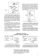
Fig. 15—Stereo output connections.
Provisions have been made to install an integrated
multiplex adapter on the top surface of the MR-65 chas-
sis. After the F.C.C. has published standards for stereo
multiplex, Mclntosh will manufacture such an adapter.
After the multiplex adapter has been installed on the
MR-65 chassis, connections for the stereo program are
made at the STEREO-OUT jacks. A shielded cable is
plugged in the STEREO-OUT-LEFT jack and connected to
the left tuner input on the music system's preamplifier.
Plug a second shielded cable in the STEREO-OUT-RIGHT
jack of the MR-65 and connect it to the right tuner input
on the music system's preamplifier. Program volume is
controlled at the music system's preamplifier. The
volume control on the MR-65 does not operate in the
stereo modes.
It is unnecessary to connect the MONO FM output
jacks to the preamplifier if the MR-65 is connected for
stereophonic operation. The monophonic FM program is
internally connected in the MR-65 to the STEREO OUT
jacks when the MODE SELECTOR is in the FM position.
STEREO WITH AN EXTERNAL MPX ADAPTER
Fig. 16—Connections for an external MPX adapter.
The unfiltered output of the MR-65 is available at the
jack marked MPX OUT. Plug the input of the external
MPX adapter into this jack. The AC power cord for the
adapter can be plugged into the AC receptacle on the
MR-65. The MPX adapter will then be turned off when the
tuner is turned off.
FM-FM or FM-AM STEREO
Fig. 17—Connection for external tuner for stereo.
The right channel program of FM-FM stereo or FM-AM
stereo is the MR-65 program. An external tuner is used
for the left channel program. The external tuner is con-
nected by a shielded cable to the STEREO IN-LEFT jack.
The left channel program (from the external tuner
through the MR-65 switching) is plugged in the STEREO-
OUT-LEFT jack and connected to the left tuner input of
the preamplifier. The right channel program supplied
by the MR-65 is plugged in the STEREO OUT-RIGHT
jack and connected to the right tuner input of the pre-
amplifier. (See Fig. 17). The MR-65 volume control does
not operate for this method of operation.
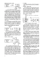
AC POWER
Plug the AC power cord in 105 volt to 125 volt, 50 to
60 cycle power line. The power used by the MR-65 is
75 watts.
ANTENNA CONNECTIONS
With the MR-65 one of three antenna systems can be
used: (1) the indoor dipole supplied with the MR-65,
(2) an outdoor FM antenna, or (3) a VHF-TV antenna. In
fringe areas best results will probably be obtained with
the use of an outdoor FM antenna. In many areas the
indoor dipole antenna is usually satisfactory. The use of
a VHF TV antenna is also effective in many installations.
Make a choice after consulting your dealer.
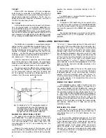
INDOOR DIPOLE ANTENNA
Fig. 18—Connection for 300 ohm antenna.
The flexible folded dipole antenna (300 ohm) sup-
plied with the MR-65 is for indoor use in urban or high
intensity signal areas. The flexibility of the thin flat wire
assembly permits it to be placed under a rug, tacked
behind the hi-fi equipment enclosure . . . or, placed in
any other convenient location. In some cases, it may be
necessary to "position" the antenna for best signal
reception. This should be done before it is permanently
located or tacked down.
To position the dipole for best results the MR-65
must be operating. The following procedure may be
followed: Connect the two leads from the dipole to the
terminals marked FM ANT on the rear of the chassis of
the MR-65; see Fig. 18.
IMPORTANT: BEFORE TURNING THE MR-65 ON,
CHECK TO SEE THAT ALL TUBES ARE FIRMLY SEATED
IN THEIR SOCKETS, AND THAT ALL PLUGS ARE COR-
RECTLY AND FIRMLY INSERTED.
Turn the power on by setting the MODE SELECTOR
to FM. Turn the AFC Control to MIN, the MUTING control
to OUT. Open the dipole to a full "T" and tune the MR-65
to a fairly weak station. Observe the SIGNAL STRENGTH
meter on the front panel as you rotate and move the di-
pole about. . . when the meter reads highest, the dipole
is in the best position for maximum signal reception for
this station. This is not a critical position; therefore you
may permanently install the antenna in a position which
most closely confirms to it.
IMPORTANT: KEEP THE DIPOLE AWAY FROM
METAL SURFACES, METAL DOORWAYS, ETC., AS THEY
USUALLY INTERFERE WITH ITS EFFICIENCY.
OUTDOOR ANTENNA
An outdoor antenna is recommended for optimum
performance in all areas. In fringe (outlying) areas, best
results will be obtained with a highly directional FM
antenna used in conjunction with a rotator. In this in-
stance, the SIGNAL STRENGTH meter may be used as an
indicator of the antenna's direction and position for
maximum signal. Connect the 300 ohm antenna to the
terminal screws marked FM ANT as in Fig. 18.
6