

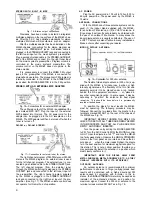


FM ANT
Either a 300 ohm balanced or 75 ohm unbalanced
antenna can be connected to the MR-65. The 300 ohm
input is balanced and connected internally through a
special balun designed by Mclntosh. The 75 ohm un-
balanced antenna connection is between one side of
the 300 ohm input and ground.
TO TV SET
A VHF television antenna may be used for FM recep-
tion. An internal switch on the MODE SELECTOR con-
nects the MR-65 between a TV antenna and a TV receiver.
With the MODE SELECTOR turned to any operating posi-
tion the VHF-TV antenna is disconnected from the TV set
and connected to the MR-65. When the MR-65 is turned
off, by rotating the MODE SELECTOR to the POWER OFF
position, the antenna is switched directly to the TV
receiver.
FUSE
The MR-65 uses a 1 ampere "Slo Blo" type fuse. The
Auxiliary AC outlet is not fused.
AC OUTLET
A maximum of 350 watts may be connected to the
AC outlet. The outlet is not fused. The MODE SELECTOR
on the front panel controls the power to this receptacle
and turns the power off in the POWER OFF position.
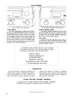
LAMPS
The dial light brightness is controlled by this switch.
Simply switch to HI or LO brightness to suit your in-
stallation.
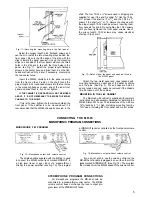
INSTALLATION INSTRUCTIONS
The MR-65 can be installed in conventional cabinets,
custom built-ins or professional equipment racks. If the
MR-65 is to be placed on a bookshelf or table-top, the
Mclntosh Model L-66 cabinet may be used to enclose the
chassis. The MR-65 is installed from the front of the
cabinet. . . not from the rear. The minimum thickness of
wood panels used to mount the MR-65 should be ¼" . . .
and panels up to 1" thick may be used.
A shelf is required to support the rear of the chassis
when the front panel is made of wood. It is important to
make a suitable cutout in the shelf for ventilation. When
mounted on a metal rack panel, a shelf is not needed.
The space in which the MR-65 will be installed should
be at least 13¾" behind the front panel to allow about
1½" for connectors. Allow at least 16½" for width and
5½" for height so there will be sufficient space for cir-
culation of air. These are inside dimensions.
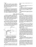
Fig. 10—Positions "A" to "C" showing the location of
the vertical center line; how the measuring tool
(mounting strip) is used to locate the horizontal
center tine, and to measure off the two points to
the right and left of the vertical center line.
MAKING THE FRONT PANEL CUTOUT
The panel is cut out using the "FRONT PANEL CUT-
OUT TEMPLATE." To position the template on the front
of the panel, it is necessary to make two locating holes
from the back (inside) of the panel using one of the
mounting strips (½" by 3½") as a measuring tool. Pro-
ceed as follows:
Measure the exact center of the proposed cut out
area and scribe a vertical center line from the top of the
panel down to the top surface of the shelf. See position
"A" in Fig. 11. Draw a horizontal line 3½" above the shelf
using one of the mounting strips as a measuring tool.
See position " B " in Fig. 11. Now—place a mounting strip
along the horizontal line to the left of the vertical center
line and mark a point 3½" left from the vertical center
line. Repeat this procedure and mark a point 3½" right
from the vertical center line. These points should now be
3½" up from the top of the shelf and 7" apart, one 3½" to
the left and one 3½" to the right of the vertical center
line. See position "C" in Fig. 11. Drill a
3
/
16
" hole at each
point—take care to hold the drill perpendicular to the front
panel so that the hole will be located accurately on the
front of the panel.
Position the template on the front of the panel using
the two locating holes to line it up correctly. Scribe the
rectangular opening on the front panel and mark the
position of the six mounting holes. Drill the six
3
/
16
"
mounting holes before cutting the panel opening. Then
cut out the opening. It is important that the cutout be
just within the lines.
MAKING THE SHELF CUTOUTS
If the installation uses a shelf, it must be cut out to
provide ventilation below the chassis. To make the cut-
out, use the "SHELF CUTOUT TEMPLATE." Locate the
center of the shelf and scribe a line from front to back.
The template is marked for panel thicknesses from ¼" to
1". Fold on the line that corresponds to the thickness of
the panel. Place it on the shelf so that it butts against the
inside of the panel. Match the center line mark on the
template to the scribed center line on the shelf. Mark the
position of the four holes and scribe the square ventila-
tion opening. Drill the four ¼" holes and cut out the
ventilation opening.
INSTALLING THE MR-65
Remove the four screws holding the MR-65 to the
shipping pallet (save these screws, you will need them if
your cabinet has a ¼" or
3
/
8
" shelf.) Remove the four
plastic feet.
In the mounting hardware package are four 6-32
flathead screws and eight 6-32 roundhead screws. Two
of the flathead screws of the proper length are used to
attach the mounting strips to the cabinet. Four of the
roundhead screws of the proper length are used to
attach the MR-65 to the cabinet and mounting strips.
The 6-32 x ½" screws are to be used with panels under
3
/
8
" in thickness. The 6-32 x ¼" screws are to be used with
panels ½" to 1" in thickness.
4