background image

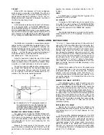
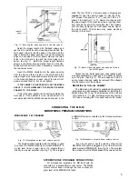
Fig. 11—Securing the mounting strip to the front panel.

Select the proper length 6-32 flathead screws and

use them to install the two mounting strips behind the

front panel. Be sure that the edge of the strip with the

clips is toward the panel opening. Line up the mounting

strips on each side of the front panel cutout so the three

holes in the strip are in line with the three holes in the

panel; see Fig. 11. Install the proper length flathead
screws in the center hole, and drive them in so the flat-

heads are flush with the panel; if necessary, countersink
the two center holes.

Insert the MR-65 carefully into the panel opening

from the front so that it rests on the shelf. Insert the

proper length 6-32 roundhead screws into the four holes
in the mounting flanges on each end of the tuner front
panel and drive them in, but do not tighten.

IF THE CABINET IS FIXED AND WILL NOT BE MOVED

ABOUT, IT IS NOT NECESSARY TO SECURE THE MR-65

CHASSIS TO THE SHELF.

If this is the case, tighten the four screws holding the

front panel. If the cabinet is to be moved about, it is

recommended that the MR-65 chassis be secured to the

shelf. The four 10-32 x ½" screws used in shipping are
supplied for use if the shelf is under

 3

/

8

". Use the 10-32

x ¾" screws if the shelf is ½" or

 5

/

8

" and the 10-32 x 1"

screws if the shelf is ¾" or

 7

/

8

". Secure the chassis with

the proper length 10-32 machine screws, inserting them
from beneath the shelf. Do not tighten the 10-32 screws

until you have tightened the front panel screws. Use of
the wrong length 10-32 screws may cause electrical

shorting in the circuit.

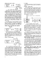
Fig. 12—Detail of how the panel end caps are fitted to

the MR-65 panel.

Attach the two metal panel end caps (packed with

mounting hardware) on each end of the panel by sliding
onto the pins. (See Fig. 3). The end caps are held by
spring tension and can easily be removed if the chassis
is to be taken out of the cabinet.

MOUNTING IN THE L-66 CABINET

The Mclntosh L-66 cabinet is supplied with complete

instructions and all necessary hardware for installing the

MR-65 Stereo FM Tuner. The dimensions of the L-66 are

16

9

/

16

" wide by 6

 11

/

16

" high (including mounting feet) by

13¾" deep, including the front panel and control knobs.

CONNECTING THE MR-65

MONOPHONIC PROGRAM CONNECTIONS

MONOPHONIC FM PROGRAM

Fig. 13—Monophonic output with volume control.

The shielded cable supplied with the MR-65 is used

to connect the MR-65 output jack marked MON-OUT to

a high level (tuner or aux.) input of a preamplifier or
directly to a power amplifier (see Fig. 13.) The program

at MON-OUT jacks is controlled by the front panel volume
control.

Fig. 14—Monophonic output without volume control.

If you do not wish to use the volume control on the

MR-65 then the cable is plugged in one or the other of the

jacks marked STEREO-OUT. (See Fig. 14). The program

then is taken from the MR-65 ahead of the volume control.

STEREOPHONIC PROGRAM CONNECTIONS

For stereophonic programs the MR-65 should be

connected to a preamplifier control center. The MR-65
volume control does not change the tuner output pro-
gram level at the STEREO OUT jacks.

5

Summary of Contents for MR65

Page 1: ...tiplex 3 Muting Adjustment 3 Output Jacks 3 Input Jacks 3 Antenna Terminals 4 Fuse 4 INSTALLATION INSTRUCTIONS 4 CONNECTING INSTRUCTIONS 5 Monophonic FM Programs 5 Stereophonic Internal Multiplex 6 Stereophonic External Multiplex 6 Stereophonic FM FM or FM AM 6 Antenna Connections 6 OPERATING INSTRUCTIONS 7 Monophonic FM Programs 7 Stereophonic Internal Multiplex 7 Stereophonic External Multiplex ...

Page 2: ......

Page 3: ...s filament hum and does not drift during warm up The newly developed AFC circuit automatically aids tuning During manual tuning the MR 65 responds as if no AFC were operating When manual tuning is com pleted a small difference usually remains between the lowest distortion setting and the manual tuning setting The new circuit brings the AFC into action gradually over approximately a three second in...

Page 4: ...UNING meter Proper adjustment is explained on page 8 under Meter Adjustments The SIGNAL STRENGTH meter is driven by the 1st IF Amplifier and indicates the relative strength of signal from each station Tuning for maximum signal strength on a weak station assists in correct tuning If a directional FM antenna with a rotator is used the SIGNAL STRENGTH meter can indicate the proper direction for the a...

Page 5: ... Two position MUTING switch Between station noise is suppressed while tuning when this switch is turned to the IN position Ultra sonic muting developed by Mclntosh electronically turns off the between station noise including the noises usually heard when tuning in and out of a station BACK PANEL FACILITIES Fig 9 Rear of chassis showing jacks terminals and adjustments MPX OUT The unfiltered output ...

Page 6: ... panel it is necessary to make two locating holes from the back inside of the panel using one of the mounting strips by 3 as a measuring tool Pro ceed as follows Measure the exact center of the proposed cut out area and scribe a vertical center line from the top of the panel down to the top surface of the shelf See position A in Fig 11 Draw a horizontal line 3 above the shelf using one of the moun...

Page 7: ... screws until you have tightened the front panel screws Use of the wrong length 10 32 screws may cause electrical shorting in the circuit Fig 12 Detail of how the panel end caps are fitted to the MR 65 panel Attach the two metal panel end caps packed with mounting hardware on each end of the panel by sliding onto the pins See Fig 3 The end caps are held by spring tension and can easily be removed ...

Page 8: ...he power used by the MR 65 is 75 watts ANTENNA CONNECTIONS With the MR 65 one of three antenna systems can be used 1 the indoor dipole supplied with the MR 65 2 an outdoor FM antenna or 3 a VHF TV antenna In fringe areas best results will probably be obtained with the use of an outdoor FM antenna In many areas the indoor dipole antenna is usually satisfactory The use of a VHF TV antenna is also ef...

Page 9: ...ring noise The AFC action is electrically delayed to permit tuning without AFC and without turning switches to disable the AFC After tuning is complete the AFC automatically locks on the station The MR 65 may be accurately tuned with out having to split hairs The very best performance with a minimum of experience or effort results from the action of the new AFC circuit For critical tuning merely t...

Page 10: ...t of the dial scale lighting can be made on the rear of the chassis Set the switch marked LAMPS for HI if you want more light and LO if you want a dimmer light plus extended lamp life GUARANTEE Mclntosh Laboratory Incorporated guarantees the mechanical and electrical workmanship and compon ents of this equipment to be free of defects for a period of 90 days from date of purchase We further guarant...

Page 11: ......

Page 12: ...LABORATORY INC 2 CHAMBERS STREET BINGHAMTON N Y Made in U S A Phone Area Code 607 723 5491 650M 2M HP Printed in U S A ...

Reviews: