background image

ADJUSTMENTS

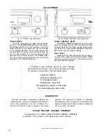
Fig. 22—TUNING meter adjustment.

TUNING METER

The meter adjustments are made with the MR-65

turned on. Turn the MODE SELECTOR to the FM position,
the MUTING switch to the OUT position, the AUTO.

FREQ. CONTROL to the extreme left, and the VOLUME

to a comfortable loudness. Turn the tuning knob so that

the dial pointer is near the center of the dial scale but

not on or near a station. The red knob under the right

panel end cap centers the pointer in the TUNING meter.

Turn the red knob until the pointer is in the center of the

black area on the TUNING meter face.

Fig. 23—SIGNAL STRENGTH meter adjustment.

SIGNAL STRENGTH METER

The SIGNAL STRENGTH adjustment is the red knob

under the left panel end cap. With the MR-65 still tuned

as above adjust this red knob until the pointer moves
over the zero (0) on the SIGNAL STRENGTH meter face.

Both meters are now properly adjusted.

DIAL LIGHTS

Adjustment of the dial scale lighting can be made on

the rear of the chassis. Set the switch marked LAMPS
for HI if you want more light, and LO if you want a dimmer

light plus extended lamp life.

GUARANTEE

Mclntosh Laboratory Incorporated guarantees the

mechanical and electrical workmanship and compon-

ents of this equipment to be free of defects for a

period of 90 days from date of purchase. We further

guarantee this equipment to perform as advertised.
This guarantee does not extend to components dam-

aged by improper use nor does it extend to transporta-

tion to and from the factory.

3-YEAR FACTORY SERVICE CONTRACT

An application for a FREE 3-YEAR FACTORY SERVICE CONTRACT

is included in the pocket on the back cover of this manual.

8

Design subject to change without notice.

The MR-65 you have purchased wilt give you years of pleasant

and satisfactory performance. If you have any questions concerning
the operation or maintenance of this tuner please contact:

Customer Service

Mclntosh Laboratory Inc.

2 Chambers Street

Binghamton, New York

Our telephone number is 723-5491.

The direct dial area code is 607.

Summary of Contents for MR65

Page 1: ...tiplex 3 Muting Adjustment 3 Output Jacks 3 Input Jacks 3 Antenna Terminals 4 Fuse 4 INSTALLATION INSTRUCTIONS 4 CONNECTING INSTRUCTIONS 5 Monophonic FM Programs 5 Stereophonic Internal Multiplex 6 Stereophonic External Multiplex 6 Stereophonic FM FM or FM AM 6 Antenna Connections 6 OPERATING INSTRUCTIONS 7 Monophonic FM Programs 7 Stereophonic Internal Multiplex 7 Stereophonic External Multiplex ...

Page 2: ......

Page 3: ...s filament hum and does not drift during warm up The newly developed AFC circuit automatically aids tuning During manual tuning the MR 65 responds as if no AFC were operating When manual tuning is com pleted a small difference usually remains between the lowest distortion setting and the manual tuning setting The new circuit brings the AFC into action gradually over approximately a three second in...

Page 4: ...UNING meter Proper adjustment is explained on page 8 under Meter Adjustments The SIGNAL STRENGTH meter is driven by the 1st IF Amplifier and indicates the relative strength of signal from each station Tuning for maximum signal strength on a weak station assists in correct tuning If a directional FM antenna with a rotator is used the SIGNAL STRENGTH meter can indicate the proper direction for the a...

Page 5: ... Two position MUTING switch Between station noise is suppressed while tuning when this switch is turned to the IN position Ultra sonic muting developed by Mclntosh electronically turns off the between station noise including the noises usually heard when tuning in and out of a station BACK PANEL FACILITIES Fig 9 Rear of chassis showing jacks terminals and adjustments MPX OUT The unfiltered output ...

Page 6: ... panel it is necessary to make two locating holes from the back inside of the panel using one of the mounting strips by 3 as a measuring tool Pro ceed as follows Measure the exact center of the proposed cut out area and scribe a vertical center line from the top of the panel down to the top surface of the shelf See position A in Fig 11 Draw a horizontal line 3 above the shelf using one of the moun...

Page 7: ... screws until you have tightened the front panel screws Use of the wrong length 10 32 screws may cause electrical shorting in the circuit Fig 12 Detail of how the panel end caps are fitted to the MR 65 panel Attach the two metal panel end caps packed with mounting hardware on each end of the panel by sliding onto the pins See Fig 3 The end caps are held by spring tension and can easily be removed ...

Page 8: ...he power used by the MR 65 is 75 watts ANTENNA CONNECTIONS With the MR 65 one of three antenna systems can be used 1 the indoor dipole supplied with the MR 65 2 an outdoor FM antenna or 3 a VHF TV antenna In fringe areas best results will probably be obtained with the use of an outdoor FM antenna In many areas the indoor dipole antenna is usually satisfactory The use of a VHF TV antenna is also ef...

Page 9: ...ring noise The AFC action is electrically delayed to permit tuning without AFC and without turning switches to disable the AFC After tuning is complete the AFC automatically locks on the station The MR 65 may be accurately tuned with out having to split hairs The very best performance with a minimum of experience or effort results from the action of the new AFC circuit For critical tuning merely t...

Page 10: ...t of the dial scale lighting can be made on the rear of the chassis Set the switch marked LAMPS for HI if you want more light and LO if you want a dimmer light plus extended lamp life GUARANTEE Mclntosh Laboratory Incorporated guarantees the mechanical and electrical workmanship and compon ents of this equipment to be free of defects for a period of 90 days from date of purchase We further guarant...

Page 11: ......

Page 12: ...LABORATORY INC 2 CHAMBERS STREET BINGHAMTON N Y Made in U S A Phone Area Code 607 723 5491 650M 2M HP Printed in U S A ...

Reviews: