


MECHANICAL SPECIFICATIONS
DIMENSIONS
Front panel —15
5
/
8
" by 5
1
/
8
". Overall depth of chassis
behind front panel is 12
5
/
16
"—A cabinet opening 14
5
/
16
"
by 4
11
/
16
" is required to insert chassis (refer to Template).
WEIGHT
Chassis only—21 lbs. 6 oz. In shipping carton—30 lbs.
12 oz.
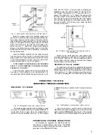
Accessories supplied with the MR-65 include:
1. Instruction book,
2. Templates for mounting,
3. Folded Dipole Antenna,
4. 6 ft. shielded signal cable,
5. Mounting hardware.
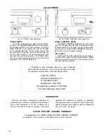
FRONT PANEL FACILITIES
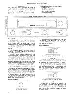
Fig. 1—Drawing of MR-65 front panel showing all controls, dial and meters.
DIAL SCALES
The MR-65 dial has two scales. The scale, below the
line, is marked in megacycles and the scale, above the
line, is a logging scale. The logging scale is used to
accurately re-tune any station. It is usually easier to keep
a record of your favorite stations by the use of the simple
numbers on the logging scale.
METERS
In the dial assembly there are two meters. The meter
on the right is the TUNING meter and the one on the left
is the SIGNAL STRENGTH meter.
A station is correctly tuned when the pointer of the
TUNING meter comes to rest anywhere in the black area
in the center of the meter face. The meter is driven by
the narrow-band discriminator. Because the meter move-
ment is magnetically damped the pointer may need
adjustment to the center of the scale at the time of
permanent installation. Under the right panel end cap is
a red knob with a decal beside it marked TUNING METER.
This knob centers the TUNING meter. Proper adjustment
is explained on page 8 under "Meter Adjustments."
The SIGNAL STRENGTH meter is driven by the 1st
IF Amplifier and indicates the relative strength of signal
from each station. Tuning for maximum signal strength
on a weak station assists in correct tuning. If a directional
FM antenna with a rotator is used the SIGNAL STRENGTH
meter can indicate the proper direction for the antenna.
The zero adjustment for the SIGNAL STRENGTH meter
is the red knob under the left end cap identified by the
SIG.ST.ADJ. decal. Proper adjustment is explained on
page 8 under "Meter Adjustment."
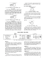
VOLUME CONTROL
The volume control permits adjustment of the pro-
gram loudness at the MONO OUT jacks on the back
panel. The STEREO OUT jacks are not controlled by the
front panel volume control.
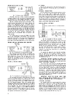
MODE SELECTOR
Fig. 3 - T h e 4 position MODE SELECTOR in the
POWER OFF position.
POWER OFF:
The MR-65 is off when the switch is turned to the
extreme left or counter clockwise position. The A.C. out-
let on the back panel is also turned off by this switch.
In the POWER OFF position any added program
source plugged into the jacks marked STEREO IN on the
back panel is connected directly to the STEREO OUT
jacks. This permits an added program source to be
played through the system without the MR-65 being
turned on.
Fig. 2—Volume Control.
Fig. 4 - M O D E SELECTOR in the FM position.
FM:
In this position all monophonic FM programs con-
nect to the back panel jacks marked MONO OUT. The
program at these jacks is controlled by the volume con-
trol on the front panel. In this position the STEREO OUT
jacks have the same monophonic program but without
the volume control.
2