


MR65 STEREO TUNER
GENERAL DESCRIPTION
Care, in the greatest degree has been devoted on this
tuner during research, design, engineering, and manu-
facture. So throughly has every detail of this equipment
been planned and carried out that even its appearance
speaks of the quality workmanship that is used through-
out.
Once you have learned to use the MR-65 . . . expe-
rienced the operation of its controls and many functions
. . . and had the opportunity to evaluate its performance
. . . you will understand how effectively traditional Mcln-
tosh design and engineering have been combined to
defeat obsolescence and provide years of trouble-free
performance.
The MR-65 is highly flexible in its operation. It will
receive either monophonic or stereophonic FM broad-
casts. A front panel volume control and two-stage audio
amplifier allow the MR-65 to operate through any type of
monophonic or stereophonic equipment including pre-
amplifiers, power amplifiers, tape recorders, etc.
All provisions have been made to connect an adapter
for any type of multiplex system the Federal Communica-
tions Commission may adopt as a result of their present
investigation and series of tests. Mclntosh will manu-
facture a built-in multiplex adapter designed to fit in a
prepared chassis opening. You can connect it with a
minimum of effort. Or, if you choose, an external multi-
plex adapter can be connected to the jack provided on the
back panel.
TECHNICAL DESCRIPTION
The MR-65 RF tuning section uses a cascode ampli-
fier, specially designed to amplify "weak signals" for less
noise and distortion. Three flat-topped IF amplifiers
reject adjacent channel interference. They give enough
gain for weak signals to operate the limiters. Two cas-
caded limiters further improve the signal-to-noise ratio.
A 4-gang capacitor and an additional tuned circuit in-
creases RF selectivity, reducing spurious or unwanted
signals.
The MR-65 uses two temperature compensated dis-
criminators. One is a narrow-band discriminator used for
ultrasonic muting, automatic frequency control, and tun-
ing meter drive. The second one is a broad-band dis-
criminator that gives nearly perfect audio performance.
A variabie-capacitance silicon diode is used in the AFC
circuit instead of a conventional tube. The silicon diode
improves AFC action, is unaffected by temperature
changes, eliminates filament hum, and does not drift
during warm-up.
The newly developed AFC circuit automatically aids
tuning. During manual tuning, the MR-65 responds as if
no AFC were operating. When manual tuning is com-
pleted a small difference usually remains between the
lowest distortion setting and the manual tuning setting.
The new circuit brings the AFC into action gradually,
over approximately a three second interval, to improve
the tuning electrically and automatically. This automatic
advantage is repeated each time a station is tuned on
the MR-65. The AFC is completely variable by a control
on the front panel.
The excellent sound quality of the MR-65 is the result
of using a two-stage, low impedance, feedback audio
amplifier. A front panel volume control permits con-
venient adjustment of output level.
The RF and IF circuits of the MR-65 are completely
shielded and exceed the FCC requirements for suppres-
sion of oscillator radiation. Either a 300 ohm or 75 ohm
antenna may be used with the MR-65. A VHF television
antenna which is suitable for FM reception can be con-
nected to the MR-65. When the tuner is turned off, it
switches the antenna back to the TV receiver (see An-
tenna Connecting Instructions).
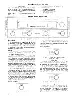
In the MR-65, a new type of mechanical tuning
assembly gives smooth flywheel tuning. With direct drive
to the tuning capacitor, which in turn drives the pointer,
backlash is almost eliminated. For smooth, quiet action
and extended life with virtually no wear, a teflon lined
pointer carriage and nylon pulleys are used in the dial
cord assembly.
ELECTRICAL SPECIFICATIONS
USABLE SENSITIVITY
3¼ microvolts at 100% modulation (± 75 kc.) for less
than 3% total noise and distortion in accordance with
IHFM Standards.
AUDIO FREQUENCY RESPONSE
Within 2 db from 20-20,000 cycles.
DISTORTION
Less than 3% for 100% modulation (accuracy of the best
available test equipment is not guaranteed below 3%).
CAPTURE RATIO
1 to 0.7.
MUTING
At least 60 db noise reduction between stations.
OSCILLATOR DRIFT
Less than 25 kc. with AFC disabled; negligible with
AFC in operation.
IMAGE REJECTION
Better than 80 db at 90 mc.; better than 70 db at 105 mc.
HUM
Better than 65 db below 100% modulation.
OUTPUT
Approximately 4 volts; low impedance.
ANTENNA INPUTS
300 ohms balanced; 75 ohms unbalanced.
POWER CONSUMPTION
75 watts, 105 to 125 volts, 50-60 cycles.
TUBE COMPLEMENT
6BN4A RF Amplifier 6SC6 2nd Limiter
6BN4A Oscillator 6BN8 Squelch amplifier
and AGC Clamp
12AT7 Mixer 6C4 Meter
(3) 6AU6 IF Amplifiers 6U8A Audio amplifier
6AU6 1st Limiter EZ80/6V4 Rectifier
1