


McHale
R62-72 & R68-78
Twin-Rotor Rake
39
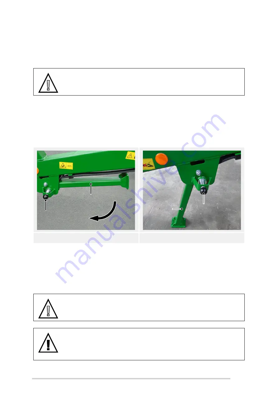
6.8 Drawbar stand
The drawbar stand must be used every time the machine is disconnected from the
tractor.
Before disconnecting from the tractor, lower the leg stand using the spring-loaded lock
pin, into the storage position, as shown.
Ensure that the stand lock pin is properly secured in the hole provided to prevent the
stand from collapse. While using the machine, ensure that the stand (1) is fully elevated
against the drawbar with the spring-loaded lock pin (2) secured in the transport position.
Once the drawbar is elevated, the stand can be moved easily between positions by
simply retracting the spring loaded pin and rotating the stand until the pin re-engages.
Always ensure the pin is positively engaged in the stand, in either position.
6.9 PTO shaft adjustment & maintenance
CAUTION: The drawbar stand must be rested on a solid footing
The machine and stand must be rested on a solid footing, on level
ground and pinned securely before disconnecting from the tractor.
Drawbar stand up (transport position)
Drawbar stand down (storage position)
CAUTION: Ensure the tractor is shut down
Ensure that the tractor engine has been shut down, the key removed
and the brakes applied before carrying out the following procedure.
WARNING: Measure distance between PTO stub shafts first
Never connect a PTO shaft on a new machine/tractor combination
without first measuring the shortest distance between PTO stub shafts,
otherwise severe damage can occur.
2
1
1
2