Chapter 3
Device views
10
3
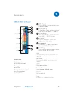
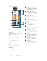
UBR-01 | Mk II front view
MS/TP
LAN
B+
–
PWR
+
A-
GND
S3
S2
S1
TX
RX
ST.
PWR.
Reset
UBR-01 |
Mk II
Universal Gateway
+24
GND
B+
A-
Shld
AGND
Reset
Link/Activity
Netzwerk
Netzteil
MS/TP
DIP-Schalter
LED
6
10/100 MBit/s
5
4
3
1
2
Status LED:
Red for approx. 6 s:
Self test after switching on
Flashing green:
Normal state
Flashing alternately red and green:
during the reset process
(see chap. Reset)
1
PWR. (Power)
This green LED lights up when the power
supply is activated..
2
RX (MS/TP RxD)
This yellow LED lights up when the router
receives data from the MS/TP network.
3
TX (MS/TP TxD)
This yellow LED lights up when the router
sends data to the MS/TP network.
4
ST. (Status)
This multi-coloured LED shows the
system status of the router.
5
10/100 MBit/s
This yellow LED indicates the speed of
the connection to the network.
6
Link/Activity
This green LED indicates the status of the
network connection and activity.
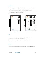
LED
Indication of the system status of the router with
four LEDs
DIP switches
Activation of bus termination and network bias
resistors
MS/TP
4-pole Weidmüller socket
Power unit
2-pole connection to voltage supply
Network
RJ45 socket (LAN)
Reset
Reset button to restore factory settings
Device views
Summary of Contents for UBR-01 MK II
Page 57: ......


