


Part No. 113489 (W10185535)
3 - 02/22/08 - 0
Suggested Cleaning Schedule
Every Third or Fourth Load
Clean the lint screen every third or fourth load. A clogged lint
screen will cause poor dryer performance. The lint door/
drawer is located just below the loading door of the dryer.
Open the lint door/drawer, brush the lint off the lint screen,
and remove the lint. Inspect lint screen and replace if torn.
NOTE:
To remove the lint drawer from the dryer first pull the
screen out roughly half way and lift the clip on the lower left
side of the lint drawer up. Now you will be able to pull the
lint drawer completely out.
IMPORTANT:
The frequency of cleaning the lint screen can
best be determined from experience at each location.
Weekly
Clean lint accumulation from lint chamber, thermostat, and
microprocessor temperature sensor area.
90 Days
Remove lint from gas valve burner area with a dusting brush
or vacuum cleaner attachment.
Clean any lint accumulation in and around the motor(s) casing
opening.
NOTE:
To prevent damage, avoid cleaning and/or touching
ignitor/flame-probe assembly.
Every 6 Months
Inspect and remove lint accumulation in customer furnished
exhaust ductwork system and from dryer’s internal exhaust
ducting.
NOTE:
Do not obstruct the flow of combustion and
ventilation air. Check back draft dampers in the exhaust
ductwork. Inspect and remove any lint accumulation, which
can cause the damper to bind or stick.
A back draft damper that is sticking partially closed can
result in slow drying and shutdown of heat circuit safety
switches or thermostats.
When cleaning the dryer cabinet(s), avoid using harsh
abrasives. A product intended for the cleaning of
appliances is recommended.
Adjustments
7 Days After Installation
and Every 12 Months Thereafter
Inspect bolts, nuts, screws, setscrews, grounding
connections and nonpermanent gas connections (unions,
shutoff valves, and orifices). Belts should be examined.
Cracked or seriously frayed belts should be replaced.
Complete an operational check of controls and valves.
Complete an operational check of all safety devices (lint door/
drawer switch, door switches, sail switch, and hi-limit
thermostats).
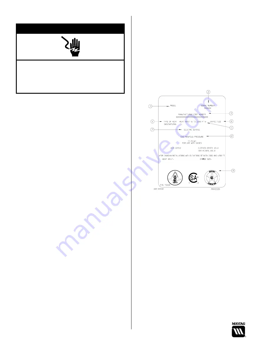
Data Label Information ________________
Standard Label
When contacting Maytag, the information on the data label is
required to ensure proper service/parts assistance. The data
label is located at the lower left rear of the dryer behind the
back guard.
1.
Model Number
– This describes the style of dryer and
type of heat (gas).
2.
Serial Number
– Allows the manufacturer to gather
information on your particular dryer.
3.
Manufacturing Code Number
– The manufacturing
code number is a number issued, which describes all
possible options on your particular model.
4.
Type of Heat
– This describes the type of heat for your
particular dryer, gas (natural gas).
5.
Heat Input
– This describes the heat input in British
thermal units per hour (Btu/hr) or kilowatts (kW).
6.
Orifice Size
– Gives the number drill size used.
7.
Electric Service
– This describes the voltage and
current rating for a particular model.
8.
Gas Manifold Pressure
– This describes the manifold
pressure taken at the gas valve tap.
9.
Applicable Approval Seal(s)
– I.E., Canadian
Standards Association International.
Electrical Shock Hazard
Disconnect power before servicing.
Replace all parts and panels before operating.
Failure to do so can result in death or electrical
shock.
▲
WARNING
!


