background image

EN

w

arninG

!

To avoid electric shock and other injury please pay 

attention to the following:

•  Do not use the device if it is damaged. Check the 

cover of the device before use. Pay extra attention to 

the insulation near the connectors. 

•  Check the connecting cables, their insulation. If the 

cables or the connectors are defective, replace them 

or do not use the device.

•  Do not use the device if it operates improperly. If you 

have doubts, take the device to a service station. 

•  Do not use the device near explosive materials (gases, 

vapors, powders)

•  Do not measure higher voltage on the device than 

indicated, not between the measuring connectors or 

between one of them and the earthing.

•  Verify the operation of the device before usage by 

measuring a known voltage. 

•  When measuring current, turn off the device before 

connecting it to the circuit. Make sure that the device 

is connected to the measured circuit serially. 

•  Only use the designated spare parts to repair the 

device. 

•  When measuring above 30 V AC RMS, 42 V peak, or 60 

V DC voltage pay extra atenntion, because there is a 

risk of electric shock. 

•  When measuring, connect the measuring pin on 

the wire first, and then the one on the device to the 

circuit. 

•  Do not use the device if the battery container lid or 

any part of the cover is missing. 

•  To avoid incorrect measuring results, electric shock 

and injury, replace the batteries right after the low 

battery symbol is lit on the display. 

Further risks:

 If any of the measuring points are 

connected to a dangerous voltage, this voltage may 

appear on the other measuring pin as well. 

w

arninG

!

To avoid damage to the device or the measured 

circuit, please note the following:

•  Disconnect the power cord and discharge the high 

capacity capacitors before measuring resistance, 

diode or continuity. 

•  Use the proper mode and threshold for measurement.

•  Before measuring current always check the fuses and 

turn off the measured circuit before connecting the 

device to it. 

•  Remove the device from the measured circuit before 

changing measuring mode with the switch.

•  Remove the device from the measured circuit before 

taking off the cover.

G

eneral


description

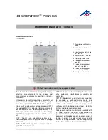
The MP-25 401 is a small size 3 1/2 digit automatic 

threshold switching digital multimeter which enables 

measuring constant and alternating voltages, alternate 

and direct currents, resistance, diode and circuit 

continuity. 

The device has the following functions:

•  Automatic nullification

•  Polarity display

•  Holding the measured data

•  Overload display

•  Automatic off switch

•  Lamp function

e

lectric

 s

yMbols

AC (alternate current)

DC (direct current)

Important security information. Read the 

manual. 

Dangerous voltage

Earthing

Fuse

Complies to EU directives

Double isolation

Low batter power

Diode

s

pecial

 s

yMbols


on


the

 d

isplay

For security reasons, the following are displayed on 

the device:

600V 

MAX

To avoid electric shock and damage 

to the device, do not connect voltage 

bigger than 600V between the 

measuring pins. 
General danger indication. Follow the 

instructions in the manual. 

600 V DC 

600 V AC 

200 mA 

MAX

The max. amount of the voltage 

measurable by the device is 600V DC or 

600VAC.  The max. measurable current 

is 200mA DC or AC.
When measuring high voltage always 

take special care. Do not touch any 

measuring pins by hand. 

Double isolation

Summary of Contents for 25401

Page 1: ... MULTIMÉTER LED LÁMPÁVAL DIGITÁLNÍ MULTIMETR S LED LAMPOU DIGITÁLNY MULTIMETER S LED LAMPOU MULTIMETR CYFROWY Z LAMPĄ LEDDIGITÁLNY MULTIMETRU DIGITAL CU LED 25401 User Manual Gebrauchsanweisung Használati utasítás Návod k použití Návod na použitie Instrukcja obsługi Manual de utilizare CZ EN DE HU SK PL RO ...

Page 2: ...pear on the other measuring pin as well Warning To avoid damage to the device or the measured circuit please note the following Disconnect the power cord and discharge the high capacity capacitors before measuring resistance diode or continuity Usethepropermodeandthresholdformeasurement Before measuring current always check the fuses and turn off the measured circuit before connecting the device t...

Page 3: ... 2 20 MΩ 2 0 2 Voltage 0 5 V Current 0 5 mA 20 mA 1 2 3 200 mA 20 mA 1 5 5 200 mA If the resistance is 30 Ω the device will beep The Front Panel 1 2 3 4 5 6 7 1 Display 3 1 2 digit LCD 1999 2 Function switch A switch that selects the different function modes or thresholds To ensure a long battery life turn off the device when not used 3 SELECT button To choose between AC and DC voltage or resistan...

Page 4: ...1 MΩ it may take a few seconds for the display to stabilize This is normal If there s a tear between the measuring pins or the circuit is open the screen will display an overflow Before measuring resistance make sure that the measuredcircuitisnotunderpowerandallcapacitors are discharged Measuring diode Set the function switch to the Ω position Press the SELECT button until you see a sign on the sc...

Page 5: ...l oder einem beschädigten Gehäuse Ersetzen Sie die Batterie so bald wie möglich wenn das entsprechende Symbol auf dem Display angezeigt wird um falsche Messergebnisse und mögliche Verletzungen zu vermeiden Weitere Warnungen Wenn eine Messspitze an eine gefährliche Spannung angeschlossen ist kann diese Spannung an der anderen Messspitze erscheinen Achtung Beachten Sie folgende Hinweise um eine Besc...

Page 6: ...60 C Probenahme ungefähr jede Sekunde Gewicht 130 g mit Batterien Antwortzeit der Digitalanzeige V AC 2 sek V DC 1 sek 0 Ω 200 kΩ 1 sek 200 kΩ 2 MΩ 2 sek 2 MΩ 20 MΩ 5 sek Relative Luftfeuchtigkeit alle Bereiche außer 20 MΩ 0 90 0 C 35 C 0 70 35 C 50 C 20 MΩ Bereich 0 80 0 C 35 C 0 70 35 C 50 C Spezifikation Die Messgenauigkeit gilt für ein Jahr ab dem Zeitpunkt der Kalibrierung bei einer Temperatu...

Page 7: ...A Drücken Sie dieTaste SELECT um zu DC Modus zu wechseln Verbinden Sie das Messkabel und die Messspitze mit dem zu messenden Stromkreis Das Display zeigt den Messwert mit der Polarität der Messspitze an Anmerkung Der maximal messbare Strom beträgt 200 mA Wenn Sie einen höheren Strom messen schmilzt die eingebaute Sicherung Wechselstrom messen Stellen Sie den Funktionsschalter auf die Position mA D...

Page 8: ...getelését Amennyiben a kábel vagy a csatlakozó sérült ne használja a készüléket vagy cserélje ki a kábeleket Ne használja a műszert ha az rendellenesen működik Ha kétségei vannak vigye a készüléket szervizbe Ne használja a készüléket robbanásveszélyes környezetben gáz gőz por Ne mérjen a készüléken feltüntetett figyelmeztető jelzésnél magasabb feszültséget sem a mérőcsúcsok sem bármelyik mérőcsúcs...

Page 9: ...odásának érdekében ne csatlakoztasson 600 V nál nagyobb feszültséget a mérőcsúcsok közé Általános veszély jelzés Kövesse a leírás útmutatását 600 V DC 600 V AC 200 mA MAX A készülék által mérhető max feszült ség 600 V DC vagy 600 VAC A max mérhető áram 200 mA DC vagy AC Nagy feszültségek mérésénél járjon el különös figyelemmel Kézzel ne érintse meg egyik mérőcsúcsot sem Kettős szigetelés Jellemzők...

Page 10: ...s bemenő mérőpontja pozitív 7 Mérőkábel Mérési földpont negatív A kijelző ismertetése 8 13 14 15 16 17 12 11 9 10 8 Folyamatosságmérés jelzése 9 Diódamérés jelzése 10 Automatikus méréshatár jelzése 11 Egyenfeszültség mérés jelzése 12 Váltófeszültség mérés jelzése 13 Méréstartás üzemmód jelzése 14 Elemlemerülés jelzése 15 Ellenállás mértékegység jelzése 16 Áram mértékegység jelzése 17 Feszültség mé...

Page 11: ...ésénél ügyeljen a megfelelő polaritásra Fordított behelyezésnél a készülék károsodhat Csak az előírt típusú elemet használja CR2032 Biztosítékcsere Biztosítékcsere ritkán szükséges akkor is legtöbbször felhasználói hiba miatt Biztosíték cseréjéhez csak a következőtípusúthasználja F250mA 250V Ř5x20mm A B C D E A biztosíték cseréje Kapcsolja ki a készüléket Távolítsa el az A jelű csavart vegye le a ...

Page 12: ... střídavý proud DC stejnosměrný proud Důležitá bezpečnostní informace Prečítjate si popis Přítomnost nebezpečného napětí Uzemnění Pojistka Vyhovuje předpisům EU Dvojitá izolace Nízká úroveň napětí baterie Dioda Speciální označení na přístroji Z bezpečnostním důvodů můžete na přístroji nalézt následující nápisy 600 V MAX Abyste se vyhnuli úrazu elektrickým proudem a poškození zařízení nepřipojujte ...

Page 13: ...ní při měření napětí odporu proudu 200 mA testu diody 7 Měřicí kabel uzemnění měření negativní Seznámení se s displejem 8 13 14 15 16 17 12 11 9 10 Signalizace testu kontinuity 8 Signalizace testu diody 9 Signalizace automatického rozsahu měření 10 Signalizace měření stejnosměrného napětí 11 Signalizace měření střídavého napětí 12 Signalizace režimu udržení dat 13 Signalizace slabé baterie 14 Sign...

Page 14: ...řeného obvodu Před výměnou baterie vypněte přístroj OFF Při vložený nových baterií dbejte na správnou polaritu V případě nesprávného vložení se přístroj může poškodit Používejte pouze předepsaný druh baterie CR2032 Výměna pojistky Výměna pojistky je nutná zriadkavo většinou je nutná kvůli nesprávnému používání K výměně používejte pouze následující typ F250 mA 250 V Ř5x20 mm A B C D E Výměna Vypnět...

Page 15: ...davého napätia jednosmerného a striedavéhoprúdu odporu diodyakontinuity Obsahuje nasledovné funkcie Automatické vynulovanie Označenie polarity Nameraná databáza Indikátor napätia Automatické vypnutie Funkcia lampy Elektrické symboly AC striedavý prúd DC jednosmerný prúd Dôležitá bezpečnostná informácia Prečítajte si opis Prítomnosť nebezpečného napätia Uzemenie Poistka Je vhodný predpisov EU Dvoji...

Page 16: ...lačením gombíku hodnota označená na monitore sa stne ponechaná Opakovaným stlačením gombíku môžeme pokračovať v meraní Tiež tento gombík slúži na štartovanie pohotovostného režimu zariadenia 5 tlačidlo na používanie funkcie lampa stlačte tento gombík dlhšie ako 2 sekúnd Vypnite s takým istým spôsobom Ak medzitým nestlačíte gombík lampa sa vypne po 15 sekúnd 6 Merací štít napätie odpor prúd 200 mA ...

Page 17: ...diodu merací štít pripojte na anódu a meraciu šnúru na katódu diody Napätie diody je zobrazení na monitore Meranie oznam kontinuity Nastavte spínač prevádzkového režimu do polohe Ω Potlačte gombík SELECT kým na monitore vidíte znak Pripojte meraciu šnúru a merací štít na prúd merania Ak odpor je menší ako 30 Ω môžete počuť zvukový signál Automatické vypnutie Ak zariadenie nepoužívate v zapnutom st...

Page 18: ...o pomiaru użyj odpowiedniego trybu i progu Przed pomiarem prądu zawsze sprawdzaj bezpieczniki Wyłącz obwód pomiarowy zanim podłączysz do niego urządzenie Odłącz urządzenie z mierzonego obwodu przed zmianą trybu pomiaru Przed usunięciem pokrywy odłącz urządzenie z mierzonego obwodu Opis ogólny MP 25 401 jest multimetrem cyfrowym o małym rozmiarze z 31 2 cyfrowym wyświetlaczem i automatyczną zmianą ...

Page 19: ... 1 Wyświetlacz 3 1 2 cyfrowy LCD 1999 2 Przełącznik funkcji Przełącznik za pomocą którego można wybierać różne tryby lub progi Aby zapewnić długą żywotność baterii wyłącz urządzenie OFF gdy nie jest w użyciu 3 Przycisk SELECT Za pomocą tego przycisku można wybrać między AC a DC oraz między funkcjami rezystancji diody ciągłości 4 Przycisk HOLD Naciśnięcie tego przycisku powoduje przytrzymanie wynik...

Page 20: ...zacja wyświetlacza może potrwać kilka sekund To jest nor malne Jeśli między końcówkami pomiarowymi pojawi się rozdarcie lub obwód jest otwarty na ekranie pojawi się przelew Przed pomiarem rezystancji upewnij się że mierzony obwód nie jest pod napięciem i wszystkie kondensatory są rozładowane Pomiar diody Ustaw przełącznik funkcji w pozycji Ω Naciśnij przycisk SELECT aż na wyświetlaczu pojawi się z...

Page 21: ... apărea la celălat vârf de testare Atenţie În scopul de a evita deteriorarea instrumentului şi circuitul care urmează să fie măsurate ţineţi cont de următoarele Deconectaţi cablul de alimentare cu energie şi descărcaţi condensatorii de mare capacitate înainte de utilizarea modului de măsurare rezistenţă diode sau de continuitate Utilizaţi modurile adecvate şi domeniile corespunzătoare măsurătorilo...

Page 22: ...0Ω atunci scoate semnal sonor Descrierea plăcii frontale 1 2 3 4 5 6 7 1 Afişaj LCD cu 3şi 1 2 cifre 1999 2 Comutator de moduri Cu acest comutator putem regla modurile instrumentului respectiv domeniile de măsurat În scopul de a creşte durata de viaţă a bateriei atunci când nu folosiţi opriţi instrumentul OFF 3 Butonul SELECT Cu acest buton putem alege dintre modurile de tensiune AC sau DC respect...

Page 23: ...ra câteva secunde până când afişajul se stabilizează Acest lucru este normal În cazul în care între vârfurile de măsură se găseşte ruptură sau circuitul este deschis afişajul indică revărsare Când măsuraţi rezistenţă înainte asiguraţi vă că circuitul nu este sub tensiune iar fiecare condensator să fie descărcat Măsurarea diodelor Aşează comutatorul de moduri în poziţia Ω Apasă butonul SELECT până ...

Page 24: ......

Reviews: