background image


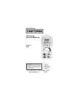
METRA

CLIP 86


CLAMP MULTIMETER 

User’s manual 

E N G L IS H  

Summary of Contents for M312J

Page 1: ...METRACLIP 86 CLAMP MULTIMETER User s manual ENGLISH ...

Page 2: ...tivation of the HOLD mode 18 2 6 KEY 18 3 USE 19 3 1 COMMISSIONING 19 3 2 STARTING UP THECLAMP MULTIMETER 20 3 3 SWITCHING THECLAMP MULTIMETER 20 3 4 CONFIGURATION 20 3 4 1 Programming of the maximum resistance allowed for a continuity 21 3 4 2 De activation of automatic switching off Auto Power OFF 21 3 4 3 Programming of the current threshold for the True INRUSH measurement 21 3 4 4 Default conf...

Page 3: ...CONDITIONS 34 4 2 1 DC voltage measurement 34 4 2 2 AC voltage measurement 35 4 2 3 AC DC voltage measurement 36 4 2 4 DC current measurement 36 4 2 5 AC current measurement 37 4 2 6 AC DC intensity measurement 37 4 2 7 True Inrush measurement 38 4 2 8 Continuity measurement 38 4 2 9 Resistance measurement 38 4 2 10 Diode test 39 4 2 11 Active DC power measurements 39 4 2 12 Active AC power measur...

Page 4: ...timeter METRACLIP 86 English 4 7 VARIATIONS INTHE DOMAINOF USE 48 5 MAINTENANCE 49 5 1 CLEANING 49 5 2 REPLACEMENT OF THEBATTERY 49 5 3 METROLOGICALCHECK 49 5 4 REPAIR 49 6 WARRANTY 50 7 DELIVERY CONDITION 50 4 ...

Page 5: ...symbol is encountered Application or withdrawal authorized on uninsulated or bare conductors at dangerous voltages 9 V battery The CE marking indicates compliance with European directives Double insulation or reinforced insulation Selective sorting of wastes for the recycling of electrical and electronic equipment within the European Union In conformity with directive DEEE 2002 96 EC this equipmen...

Page 6: ... the voltage or category exceeds those mentioned Do not exceed the rated maximum voltages and currents between terminals or with respect to earth Do not use the instrument if it appears to be damaged incomplete or not properly closed Before each use check the condition of the insulation on the leads housing and accessories Any element of which the insulation is deteriorated even partially must be ...

Page 7: ...cted from all dangerous voltages MEASUREMENT CATEGORIES Definitions of the measurement categories CAT II Circuits directly connected to the low voltage installation Example power supply to household electrical appliances and portable tools CAT III Power supply circuits in the installation of the building Example distribution panel circuit breakers fixed industrial machines or devices CAT IV Circui...

Page 8: ...rush Voltage measurement Frequency measurement Measurement of level of harmonics THD Continuity test with buzzer Resistance measurement Diode test Power measurements W VA var and PF Indication of the order of the phases Item Designation See 1 Jaws with centring marks see connection principles 3 5 to 3 14 2 Physical guard 3 Switch 1 1 4 Function keys 2 5 Display unit 1 3 6 Terminals 1 4 7 Trigger F...

Page 9: ...re described in the table below Figure 2 the switch Item Function See 1 OFF mode Switches the clamp multimeter off 3 3 2 AC DC AC DC voltage measurement V 3 5 3 Continuity test Resistance measurement Ω Diode test 3 6 3 7 3 8 4 AC DC AC DC current measurement A 3 9 5 Power measurements W var VA and calculation of the power factor PF AC DC AC DC 3 11 6 Indicator of the order of the phases 3 12 1 2 3...

Page 10: ...ohmmeter function 2 1 3 9 2 3 6 1 2 Selection of the type of measurement AC DC AC DC Selection of single phase or three phase measurement 2 2 3 Activation or de activation of the backlighting of the display unit 2 3 4 Activation or de activation of the MAX MIN PEAK mode Activation or de activation of the INRUSH mode in A 2 4 5 Measurements of frequency Hz of the level of harmonics THD Display of t...

Page 11: ...12 3 Display of the MAX MIN PEAK modes 2 4 4 Type of measurement AC or DC 2 2 5 Total three phase power measurements 3 11 2 6 Display of the selected modes switch 3 5 7 Spent battery indication 5 2 1 3 1 The symbols of the display unit Symbol Designation AC Alternating current or voltage DC Direct current or voltage AC DC Alternating and direct current or voltage REL Relative value with respect to...

Page 12: ...prefix var Reactive power VA Apparent power PF Power factor THDf Total harmonic distortion with respect to the fundamental THDr Total harmonic distortion with respect to the true RMS value of the signal Indicator of order to the phases Compensation of the resistance of the leads Continuity test Diode test Permanent display automatic switching off de activated Spent battery indicator The display of...

Page 13: ...ect complementarity with them this makes navigation simple and intuitive for looking up all measurement results It is possible for example to look up in turn the MAX MIN etc values of the RMS voltage alone or else look up in turn all of the MAX or MIN or PEAK values of all power results W VA var etc In this section the icon represents the possible positions of the switch for which the key concerne...

Page 14: ...n of the zero see 3 9 2 Remark this mode operates if the MAX MIN PEAK or HOLD modes short press are first desactivated Sustained to perform automatic compensation of the resistance of the leads see 3 6 1 See also 2 4 2 and 2 5 1 for the action key with the action of the key and with the action of the key 2 2 KEY SECOND FUNCTION This key is used to select the type of measurement AC DC AC DC and the...

Page 15: ...ht the display unit Successive presses on serve to activate or de activate the backlighting of the screen Remark the backlighting is switched off automatically at the end of 2 minutes 2 4 KEY 2 4 1 In the normal mode This key activates detection of the MAX MIN PEAK and PEAK values of the measurements made Max and Min are the extreme mean values in DC and the extreme RMS values in AC Peak is the ma...

Page 16: ...isplay the MAX or MIN value successively to return to display of the present measurement without exiting from the mode the values already detected are not erased long 2 sec to exit from the MAX MIN PEAK mode The values previously recorded are then erased Remark if the HOLD function is activated it is not possible to exit from the MAX MIN PEAK mode The HOLD function must first be de activated Remar...

Page 17: ...ent measurement is displayed after the calculations stage backlighting off Remark the A symbol flashes to indicate surveillance of the signal to exit from the True INRUSH mode return to simple current measurement short 2 sec Note a short press is functional only if an True Inrush value has been detected to display the PEAK value of the current to display the PEAK value of the current to display th...

Page 18: ...t to select THDf THDr or the frequency of the fundamental 2 5 2 The Hz function activation of the HOLD mode Successive presses on serves short to store the frequency to display successively the stored frequency then the voltage or the current to display in turn the stored values of THDf then of THDr then of the frequency of the fundamental 2 6 KEY This key is used to display and store the referenc...

Page 19: ...erence The ΔRef symbol is displayed to display the current value The ΔRef symbol blinks long 2 sec to exit from the ΔREL mode Remark the Relative mode ΔREL function can be used with the functions of the MAX MIN PEAK mode 3 USE 3 1 COMMISSIONING Insert the battery supplied with the device as follows 1 Using a screwdriver unscrew the screw of the battery compartment cover item 1 on the back of the h...

Page 20: ...ITCHING THE CLAMP MULTIMETER The clamp multimeter can be switched off either manually by setting the switch to OFF or automatically after ten minutes with no action on the switch and or the keys Thirty 30 seconds before the device is switched off an audible signal sounds intermittently To re activate the device press any key or turn the switch 3 4 CONFIGURATION As a safety measure and to avoid rep...

Page 21: ...activation of automatic switching off Auto Power OFF To de activate automatic switching off In the OFF position hold the key down while turning the switch to until the full screen display ends and a beep is emitted to enter the configuration mode The symbol is displayed When the key is released the device is in the voltmeter function in the normal mode The return to Auto Power OFF takes place when...

Page 22: ...e full screen display ends and a beep is emitted to enter the configuration mode The rSt symbol is displayed After 2 s the clamp emits a double beep then all of the symbols of the screen are displayed until the key is released The default parameters are then restored Continuity detection threshold 40Ω True Inrush triggering threshold 10 3 5 VOLTAGE MEASUREMENT V To measure a voltage proceed as fol...

Page 23: ... is off and any capacitors have been discharged 1 Set the switch to the symbol is displayed 2 Connect the black lead to the COM terminal and the red lead to 3 Place the test probes or the crocodile clips on the terminals of the circuit or component to be tested An audible signal is emitted if there is continuity and the measured value is displayed on the screen 23 ...

Page 24: ...splayed The value displayed is stored Remark the correction value is stored only if it is 2 Ω Above 2 Ω the value displayed blinks and is not stored 3 7 RESISTANCE MEASUREMENT Ω Warning Before making a resistance measurement make sure that the circuit is cold and any capacitors have been discharged 1 Set the switch to and press the key The Ω symbol is displayed 2 Connect the black lead to the COM ...

Page 25: ...ned by pressing the trigger on the body of the device The arrow on the jaws of the clamp see the diagram below must point in the presumed direction of flow of the current from the generator to the load Make sure that the jaws have closed correctly Remark the measurement results are optimal when the conductor is centred in the jaws aligned with the centring marks The device automatically selects AC...

Page 26: ...position during the whole procedure so that the correction value will be exact Press the key until the device emits a double beep and displays a value near 0 The correction value is stored until the clamp is powered down Remark the correction is effected only if the value displayed is 6 A otherwise the value displayed blinks and is not stored The clamp must be recalibrated see 5 3 Step 2 to make a...

Page 27: ...f the True Inrush current is displayed and the A symbol flashes 3 After detection and acquisition for 100 ms the RMS value of the True Inrush current is displayed along with the PEAK PEAK values subsequently 4 A long press on the key or a change of function leads to exiting from the True Inrush mode Remark the triggering threshold in A is 6A if the initial current is zero starting of installation ...

Page 28: ...mp only the corresponding conductor respecting the direction The measurement is displayed on screen 3 11 2 Balanced three phase power measurement 1 Set the switch to and select VA var or PF by pressing the key until the desired choice is reached 2 Press the yellow key until the symbol is displayed 3 The device automatically displays AC DC To select AC DC or AC DC press the yellow key until the des...

Page 29: ... order of the phases proceed as follows Step 1 determination of a reference period 1 Set the switch to The rdy symbol is displayed the device is ready for the first phase order determination measurement 2 Connect the black lead with crocodile clip to the COM terminal and the red lead with test probe to 3 Connect the crocodile clip to the presumed L1 phase and apply the red test probe to the presum...

Page 30: ...ks and turns clockwise 0 3 2 1 when the direction of rotation is reversed The 0 symbol blinks and turns anticlockwise Remark if the order of the phases has not been determined the device emits a beep and displays the Err message Repeat the procedure from 4 3 13 FREQUENCY MEASUREMENT HZ The frequency measurement is available in V W and A for AC and AC DC quantities The measurement is based on a cou...

Page 31: ...d choice is reached 3 Encircle only the conductor concerned with the clamp The measured value is displayed on the screen 3 13 3 Measurement of frequency in power In the single phase AC or AC DC Power W setting it is possible to display the frequency of the voltage of the signal on the terminals In the balanced three phase AC or AC DC Power W setting it is possible to display the frequency of the p...

Page 32: ...and press and hold 2s the key The THDf symbol is displayed To select THDr press the key again The THDr symbol is displayed To select the frequency of the fundamental press the key again The Hz symbol is displayed 2 Connect the black lead to the COM terminal and the red lead to 3 Place the test probes or the crocodile clips on the terminals of the circuit to be measured The measurement is displayed...

Page 33: ...English Clamp Multimeter METRACLIP 86 The measurement is displayed on screen 33 ...

Page 34: ...acent conductors none Alternating magnetic field none Electric field none 4 2 CHARACTERISTICS UNDER THE REFERENCE CONDITIONS The uncertainties are expressed in x of the reading R y points pt 4 2 1 DC voltage measurement Measurement range 0 00 V to 59 99 V 60 0 V to 599 9 V 600 V to 1000 V 1 Specified measurement range 0 to 100 of the measurement range Uncertainties from 0 00V to 5 99V 1 R 10 pt fr...

Page 35: ...ent range 2 0 to 100 of the measurement range Uncertainties from 0 15V to 5 99V 1 R 10 pt from 6 00V to 59 99V 1 R 3 pt 1 R 3 pt Resolution 0 01V 0 1V 1V Input impedance 10MΩ Note 1 The display indicates OL above 1000V 1400V in PEAK mode Above 1000V a repetitive beep indicates that the voltage being measured is greater than the safety voltage for which the device is guaranteed The display indicate...

Page 36: ... Bandwidth in AC 3 kHz Note 2 Any value between zero and the min threshold of the measurement range 0 15V is forced to on the display Specific characteristics in MAX MIN mode in voltage from 10Hz to 1kHz in AC and AC DC and from 0 30V Uncertainties add 1 R to the values in the tables above Capture time of the extrema approximately 100ms Specific characteristics in PEAK mode in voltage from 10Hz to...

Page 37: ...kHz Note 2 Any value between zero and the min threshold of the measurement range 0 15V is forced to on the display Residual current at zero 150mA 4 2 6 AC DC intensity measurement Measurement range 2 0 15 A to 59 99 A 60 0 A to 599 9 A AC 600 A DC or PEAK 600 A to 900 A 1 Specified measurement range 0 to 100 of the measurement range Uncertainties 2 zero corrected 1 R 10 pt 1 R 3 pt Resolution 0 01...

Page 38: ...surement range 6 A to 600 A AC 6 A to 900 A DC Specified measurement range 0 to 100 of the measurement range Uncertainties 5 R 5 pt Resolution 1 A Specific characteristics in PEAK mode in True Inrush from 10Hz to 400 Hz in AC Uncertainties add 1 5 R 0 5A to the values in the tables above PEAK capture time 1ms min to 1 5ms max 4 2 8 Continuity measurement Measurement range 0 0Ω to 599 9 Ω Open circ...

Page 39: ...nt range 1 to 100 of the measurement range Uncertainties 1 R 3 pt Resolution 0 001V Measurement current 0 55 mA Indication junction reversed or open circuit Display of OL when the measured voltage 3 199V Note The sign is disabled for the diode test function 4 2 11 Active DC power measurements Measurement range 2 0 W to 5999 W 6 00 kW to 59 99 kW 60 0 kW to 599 9 kW 600 kW to 900 kW 1 Specified mea...

Page 40: ...te 1 Display of O L Above 600kW in single phase 1000V x 600A Bandwidth in AC in voltage 3 kHz in current 3 kHz Notes 2 and 3 of the previous apply Note 4 Any power measured less than 5W is regarded as zero and causes the display of dashes If the voltage is less than 0 15V or if the current is less than 0 15A the power measured is regarded as zero and causes the display of dashes Note 5 The active ...

Page 41: ...40 4 2 13 Active AC DC power measurements Measurement range 2 4 5 W to 5999 W 6 00 kW to 59 99 kW 60 0 kW to 599 9 kW 600 kW to 900 kW 1 Specified measurement range 1 to 100 of the measurement range 0 to 100 of the measurement range Uncertainties 3 7 2 R 10 pt 2 R 3 pt Resolution 1W 10W 100W 1000W Note 1 Display of O L Above 900kW in single phase 1000V x 900A Bandwidth in AC in voltage 3 kHz in cu...

Page 42: ...le phase 1000 V x 600 A Bandwidth in AC in voltage 3 kHz in current 3 kHz Notes 2 3 and 4 of the previous apply 4 2 15 Measurement of apparent AC DC power Measurement range 2 4 5 VA to 5999 VA 6 00 kVA to 59 99 kVA 60 0 kVA to 599 9 kVA 600 kVA to 900 kVA 1 Specified measurement range 1 to 100 of the measurement range 0 to 100 of the measurement range Uncertainties 3 2 R 10 pt 2 R 3 pt Resolution ...

Page 43: ...hile in balanced three phase it is determined by the calculation on the samples Note 6 Signs of reactive powers according to the four quadrant rule 4 2 12 Quadrant 1 Reactive power Q sign Quadrant 2 Reactive power Q sign Quadrant 3 Reactive power Q sign Quadrant 4 Reactive power Q sign Note 8 In single phase with deformed signals THD and harmonics uncertainties are guaranted since Ф 30 Additionals...

Page 44: ...ent range Uncertainties 7 3 R 3 pt 2 R 3 pt Resolution 0 01 Note 1 If one of the terms in the calculation of the power factor is displayed as OL or forced to zero the display of the power factor is an indeterminate value Note 7 of the previous apply Note 9 Sign of the power factor according to the four quadrant rule 4 2 12 Quadrant 1 Power factor PF sign inductive system Cos Φ sign Quadrant 2 Powe...

Page 45: ...ng range is limited to 1kHz If the level of the signal is too low 10 of the range or U 10V or I 10A or if the frequency is less than 5Hz the device cannot determine the frequency and displays dashes Specific characteristics in MAX MIN mode from 10Hz to 1kHz Uncertainties add 1 R to the values of the table above Capture time of the extrema approximately 100ms 4 2 20 Characteristics in THDr Measurem...

Page 46: ...z to 400Hz Acceptable voltage range 50V to 1 000V Duration of acquisition of the reference period 500ms Duration of validity of the reference period information approximately 10s at 50Hz approximately 2s to 400Hz Duration of acquisition of the measurement period display of the order of the phases 500ms Acceptable phase unbalance 10 Acceptable amplitude unbalance 20 Acceptable level of harmonics in...

Page 47: ...F22 Mean life 120 hours without backlighting Duration of operation before automatic switching off After 10 minutes without action on the switch and or keys 4 6 COMPLIANCE WITH INTERNATIONAL STANDARDS Electric safety Compliant with standards IEC 61010 1 IEC 61010 2 30 and IEC 61010 2 32 1000V CAT III or 600V CAT IV Electromagnetic compatibility Compliant with standard EN 61326 1 Classification resi...

Page 48: ...Frequency 10 Hz 1 kHz 1 kHz 3 kHz 10 Hz 400 Hz 400 Hz 3 kHz V A 1 R 1 pt 8 R 1 pt 1 R 1 pt 4 R 1 pt 1 R 1 pt 9 R 1 pt 1 R 1 pt 5 R 1 pt Position of the conductor in the jaws f 400 Hz Any position on the internal perimeter of the jaws A W 2 R 4 R 1 pt Adjacent conductor carrying a current of 150 A DC or RMS Conductor touching the external perimeter of the jaws A W 30 dB 20 dB Conductor enclosed by ...

Page 49: ... measurements and specifications are no longer guaranteed To replace the battery proceed as follows 1 Disconnect the measurement leads from the input terminals 2 Set the switch to OFF 3 Use a screwdriver to unscrew the screw securing the battery compartment cover to the back of the housing and open the cover see 3 1 4 Replace the battery see 3 1 5 Close the cover and screw it to the housing 5 3 ME...

Page 50: ...he explicit permission of the manufacturer s technical staff Work done on the device by a person not approved by the manufacturer Adaptation to a particular application not anticipated in the definition of the equipment or not indicated in the user s manual Damage caused by shocks falls or floods 7 DELIVERY CONDITION The METRACLIP 86 clamp multimeter is delivered in its packaging box with 2 banana...

Page 51: ...m This address is only valid in Germany Please contact our representatives or subsidiaries for service in other countries Product Support If required please contact GMC I Messtechnik GmbH Product Support Hotline Phone 49 911 8602 0 Fax 49 911 8602 709 E Mail support gossenmetrawatt com Subject to change without notice A pdf version is available on the Internet Phone 49 911 8602 111 GMC I Messtechn...

Reviews: