Chapter 2 Wiring
24
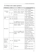
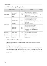
2.4.2
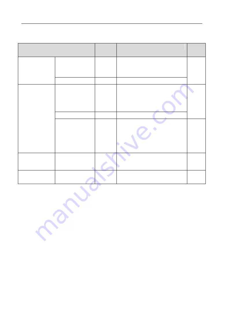
X1 terminal signal explanation
Name of signals
pin
number
function
connect
or
digital inputs
DI1/DI2/DI3
DI4/DI5
14/2/15
3/16
Photo isolation input; function is
programmable; defines by parameter
P100 to P104.
C1
COM+
1
DI power supply
(
DC12V
~
24V
)
digital output
DO1/DO2/DO3
4/17/5
Photo isolation output; maximum
output: 50mA/25V; function is
programmable; defines by parameter
P130~P132.
C2
DOCOM
18
DO common terminal
DO4+/DO4-
DO5+/DO5-
11/23
12/24
Optoelectronic isolated output,
maximum output capacity of
50mA/25V, function programmable,
digital differential output defined by
parameters
Position high
speed latch
HDI1+/HDI1-
HDI2+/HDI2-
20/7
19/6
High speed photoelectric isolation
input
Shield protection
ground
Metal case of
connector
Shielded wire for connection with
shielded cable.
2.4.3
X1 terminal interface type
The followings introduce the X1 various interface circuits and the wiring ways with the
host-controller.
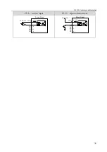
1.
Digital input interfaces (C1)
For carrying on a control, the digital input interface circuit can be constructed by switch,
relay, open-collector triode, and photo-coupler and so on. To avoid contacting problem the
relay must be chosen with low current operation. External voltage is in the range of
DC12V~24V.
Summary of Contents for EP3E Series
Page 10: ......

