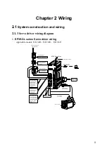


2.1 System construction and wiring
17
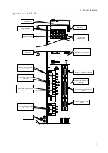
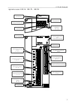
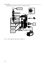
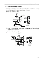
2.1.5
Main circuit wiring diagram
1.
The power supply for the servo driver GL series is a three-phase AC 220V which generally
come from three-phase AC380V power supply through a transformer.
Applicable models:
GL1A0
【
Note
】
Single phase
AC 220V
1QF
1KM
L1
L2
L3
L1C
L2C
Servo Drive
U
V
W
M
ENC
X2
Servo Motor
U
W
V
FIL
DO 2
17
DO
COM
18
DO public
interface
Servo Alarm
ALM
Main Power
ON
Main Power
OFF
1KM
1RY
1KM
PRT
1RY
D
DC24V
R
S
X1
B1
B2
P
1QF: Circuit Breaker
FIL: Noise Filter
1KM: Magnetic Contactor
1RY: Relay
PRT: Surge Absorber
D: Free-wheeling Diode
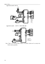
Note: There is no internal brake resistor of GL1A0, which does not need to connect
the brake resistor generally.
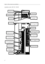
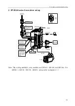
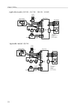
Applicable models: GL1A8
、
GL3A0
Single phase
AC 220V
1QF
External braking
resistance connection
L1
L2
L3
L1C
L2C
Servo drive
U
V
W
M
ENC
X2
Servo motor
U
W
V
FIL
DO 2
17
DO
COM
18
DO public
interface
Servo Alarm
ALM
1KM
1RY
1KM
PRT
1RY
D
DC24V
R
S
X1
B1
B2
P
1QF: Circuit Breaker
FIL: Noise Filter
1KM: Magnetic Contactor
1RY: Relay
PRT: Surge Absorber
D: Free-wheeling Diode
Internal
Braking
resistor
connection
B1
B2
P
Main Power
OFF
Main Power
ON
Summary of Contents for EP3E Series
Page 10: ......


