Chapter 2 Wiring
28
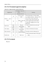
2.5.2 X2
Terminal signal description
Absolute communication encoder definition:
Signal name
Pin number / signal line
color
Function
Absolute (10 core)
Encoder
power
supply
5V
4
Red + Red and
white
The encoder uses a 5V power supply
(provided by the drive)
,
when the cable is
above 20m, in order to prevent the
encoder voltage from decreasing, the
power supply and ground wire can be
connected by multiple wires or using
thick wires.
0V
5
Black + black and
white
Signal input
SD+
1
Brown
Connect with absolute encoder signal
output
SD-
2
Brown White
Clock output
MA+
6
Green
Connect with absolute clock input
MA-
7
Green white
Outer battery pin
E+
3
Yellow
External connection with battery pin
E-
8
Yellow and white
Shielded line
FG
9
Naked wire
Connect with the shield line of the signal
cable.
2.5.3 X3 terminal
Reserve
Summary of Contents for EP3E Series
Page 10: ......

