maxon motor control
MCD EPOS P Programmable Compact Drive
Document ID: rel2895
4-19
MCD EPOS P 60 W Hardware Reference
Edition: December 2011
© 2011 maxon motor. Subject to change without prior notice.
4.2
Signal Connector (J1)
Contains smart multi-purpose digital I/Os preconfigured as…
•
“Positive Limit Switch”
•
“Negative Limit Switch”
•
“Home Switch”.
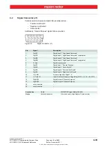
Additionally, “General Purpose” digital I/Os are provided.
Figure 4-6
Signal Connector (J1)
Pin
Signal
Description
1
DigIN7
Digital Input 7 “High Speed Command”
2
DigIN7/
Digital Input 7 “High Speed Command” complement
3
DigIN8
Digital Input 8 “High Speed Command”
4
DigIN8/
Digital Input 8 “High Speed Command” complement
5
D_Gnd
Digital signal ground
6
DigIN1
Digital Input 1 “General Purpose”
7
DigIN2
Digital Input 2 “Home Switch”
8
DigIN3
Digital Input 3 “Positive Limit Switch”
9
DigIN4
Digital Input 4 “Negative Limit Switch”
10
IN_COM
Common signal for DigIN1…4
11
+V Opto IN
Input for external supply voltage for DigOUT3…4 (+12…+24 VDC)
12
DigOUT3
Digital Output 3 “General Purpose”
13
DigOUT4
Digital Output 4 “General Purpose”
14
not connected
–
15
not connected
–
Accessories
Cable
MCD EPOS Signal Cable (326923)
Notes
Suitable connector
D-Sub connector High Density 15 poles (male)


