


maxon motor control
4-20
Document ID: rel2895
MCD EPOS P Programmable Compact Drive
Edition: December 2011
MCD EPOS P 60 W Hardware Reference
© 2011 maxon motor. Subject to change without prior notice.
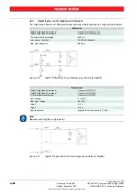
4.2.1
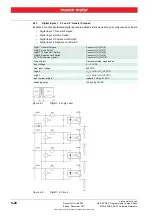
Digital Inputs 1, 2, 3 and 4 “General Purpose”
By default, the optically isolated digital inputs are defined as follows and may be configured via software.
•
Digital Input 1 “General Purpose”
•
Digital Input 2 “Home Switch”
•
Digital Input 3 “Positive Limit Switch”
•
Digital Input 4 “Negative Limit Switch”
Figure 4-7
DigIN1…4 Logic Level
Figure 4-8
DigIN1…4 Circuit
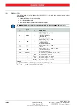
DigIN1 “General Purpose”
DigIN2 “Home Switch”
DigIN3 “Positive Limit Switch”
DigIN4 “Negative Limit Switch”
IN_COM (common signal)
Connector [J1] Pin [6]
Connector [J1] Pin [7]
Connector [J1] Pin [8]
Connector [J1] Pin [9]
Connector [J1] Pin [10]
Type of input
Optically isolated, singe-ended
Input voltage
0…+24 VDC
Max. input voltage
±30 VDC
Logic 0
| I
in
| <1 mA / | U
in
| <5 VDC
Logic 1
| I
in
| >2 mA / | U
in
| >9 VDC
Input current at logic 1
typically 3 mA @ 24 VDC
Switching delay
<300 µs @ 24 VDC


