


maxon motor control
MCD EPOS P Programmable Compact Drive
Document ID: rel2895
4-23
MCD EPOS P 60 W Hardware Reference
Edition: December 2011
© 2011 maxon motor. Subject to change without prior notice.
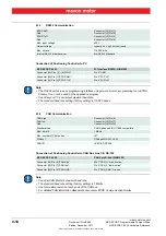
4.2.3
External Supply Input Voltage for DigOUTs
For optically isolated digital outputs, an external supply voltage must be applied. Basically, any power
supply may be used, provided it meets below stated minimal requirements.
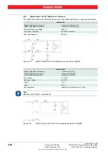
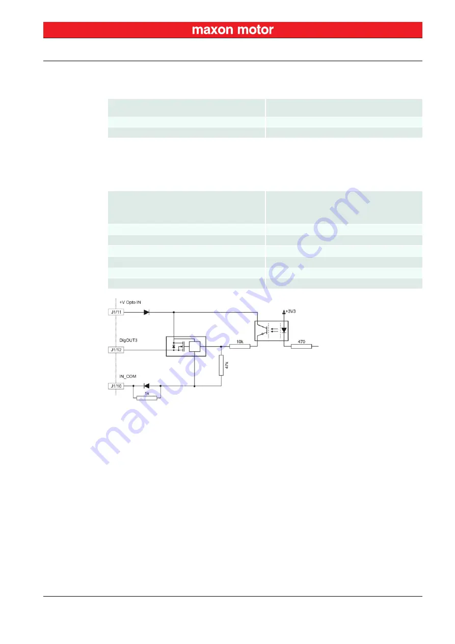
4.2.4
Digital Outputs 3 and 4 “General Purpose”
By default, the optically isolated digital outputs are defined as “General Purpose” and may be configured
via software.
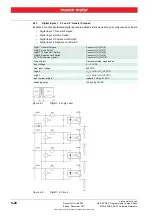
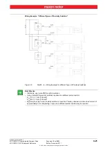
Figure 4-12
DigOUT3 Circuit – (analogously valid also for DigOUT4)
+V Opto IN
IN_COM (common signal)
Connector [J1] Pin [11]
Connector [J1] Pin [10]
Supply voltage
+12…+24 VDC
Min. current (if max. load on DigOUTs is required)
700 mA
DigOUT3
DigOUT4
+V Opto IN
IN_COM (common signal)
Connector [J1] Pin [12]
Connector [J1] Pin [13]
Connector [J1] Pin [11]
Connector [J1] Pin [10]
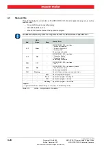
Type of output
Optically isolated, open emitter
Output voltage
U
out
≥
(+V Opto IN - 1.5 V)
Max. load current
I
load
≤
350 mA
Leakage current
I
leak
≤
50 µA
Switching delay
<300 µs @ 24 VDC
Max. inductive load
2 H @ 24 VDC; 500 mA


