


3
Installation (Continued)
Load Factors
Applications with few (up to 10)
stops and starts per day
Occasional (1/2 hr. total/day)
1.25
1.10
1.00
Intermittent (2 hrs. total/day)
1.10
1.00
0.80
8 hrs./day
1.00
0.80
0.67
24 hrs./day 0.80
0.67
.057
Applications with frequent (over 10)
stops and starts per day
Occasional (1/2 hr. total/day)
1.10
1.00
0.80
Intermittent (2 hrs. total/day)
1.00
0.80
0.67
8 hrs./day
0.80
0.67
0.57
24 hrs./day 0.67
0.57
.050
a. Overhung Loads:
Sideward (radial) force on a motor
output shaft is called overhung load.
Driving a load through a gear,
sprocket wheel, or belt pulley which
is mounted on the speed reducer
output shaft causes overhung load
on the shaft. Too much overhung
load can break the shaft or cause the
bearings to fail prematurely.
Calculate the amount of overhung
load which the speed reducer will
receive in your installation as follows:
Overhung
=
(2) x (T) x (C) x (L)
Load (Lbs) D
The terms of the above formula are as
follows:
(T) = Full Load Torque of speed
reducer, in in-lbs., from
Specifications and Performance
(C) = Coupling Factor from following
chart, accounting for type of
coupling
(D) = Pitch Diameter, in inches, of
coupling being mounted on gear
motor’s output shaft
(L) = “Leverage” Factor from following
chart, accounting for position of
coupling along length of speed
reducers output shaft
Coupling Factors
Chain Sprocket Wheel
1.00
Gear (pinion)
1.25
V-Belt Pulley
1.50
Flat Belt Pulley
2.50
“Leverage” Factors
Coupling Type
Factor
End of shaft extension
0.80
Center of shaft extension
1.00
Next to shaft extension shoulder 1.20
After calculating the amount of
overhung load expected in your
installation, compare it to the
overhung load rating.
Maximum
allowable
overhung load is 600 lbs.
If the expected amount of overhung
load is higher than the specified limit,
you must change a component or the
location of a component in your
installation to bring the overhung load
within the limit. To increase the
operating life of the speed reducer
bearings, design your installation to
reduce overhung load as much as
possible.
Excessive static
chain or belt
tension (i.e. tension present when
not running) will cause additional,
unnecessary, overhung load; set
tension no higher than
recommended by chain or belt
manufacturer.
b. On direct-coupled installations,
carefully check shaft and coupling
alignment while bolting down speed
reducer. Shim as required. Do not
depend on a flexible coupling to
compensate for misalignment.
7. Make final wiring connections
(consult nameplate on motor).
NOTE:
Output shaft may be run in
either direction by changing motor
connections. Per diagram or
instructions by motor manufacturer.
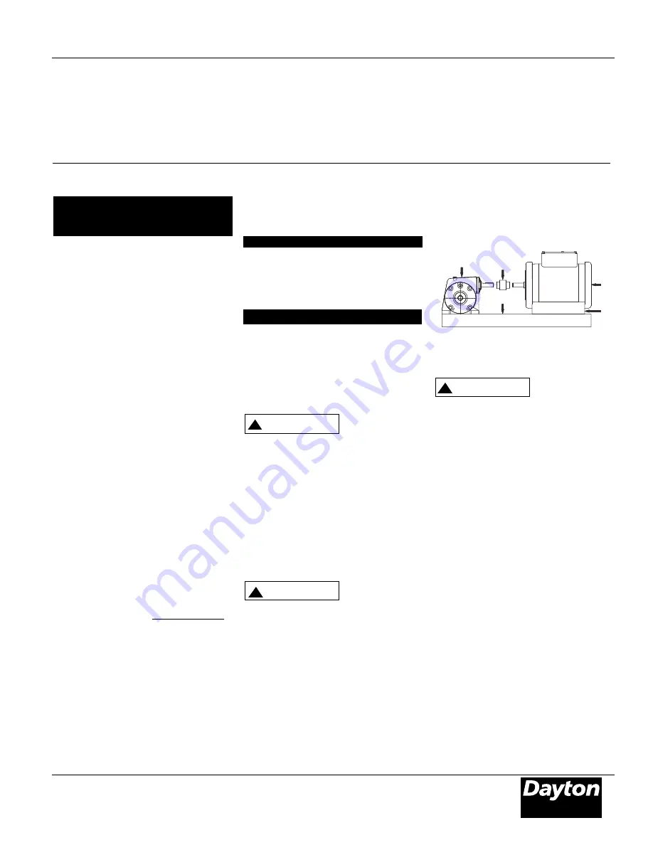
Figure 4 - Typical Installation
Maintenance
Make certain
that the power
supply is disconnected before
attempting to service or remove
any components! If the power
disconnect point is out-of
sight, lock it in the open position
and tag to prevent unexpected
application of power to
installation.
1
.
If internal parts have been replaced
on the output shaft assembly, new
adjustment for end play will be
required.
a. Reassemble unit, beginning with
the same shim stack thickness
behind the bearing cup in the
housing cover as before. Oil seal
(Ref. Figure 5 No. 20) should be
removed from cover until
shimming process is completed
and rotation checked to avoid
damage to seal from possible
repetitious disassemblies of cover.
b. Install new gasket (Ref. Figure 5
No. 18) if required.
c. As the capscrews (Ref. Figure 5 No.
21) holding the housing cover
(Ref. Figure 5 No. 19) are being
tightened, pull shaft back and
!
CAUTION
!
WARNING
Dayton Operating Instructions and Parts Manual
®
Models 2Z306F thru 2Z310F
Loading
Type of
Moderate Heavy
Service Uniform Shock
Shock
!
CAUTION
Coupling Type
Factor
!
WARNING
A
C
D
B
E
A-Reducer, B-Motor, C-Coupling, D-Mounting
Base, E-Spacers
20
Summary of Contents for Magic Finger Bagger
Page 14: ...14...
Page 15: ...15...
Page 16: ...16...
Page 17: ...17...
Page 36: ...Integral Horsepower DC Motor Installation Operating Manual 5 05 MN605 36...
Page 48: ...Section 1 General Information 2 6 Installation Operation MN605 48...
Page 66: ...66...
Page 67: ...67...
Page 68: ...68...
Page 69: ...69...
Page 70: ...70...
Page 71: ...71...
Page 72: ...72...
Page 73: ...73...
Page 74: ...74...
Page 75: ...75...
Page 76: ...76...
Page 81: ...81...
Page 84: ...DECAL REORDER SHEET DECAL NUMBER DECAL IDENTIFICATION D001 D002 D003 D004 D005 84...
Page 85: ...DECAL REORDER SHEET DECAL NUMBER DECAL IDENTIFICATION D006 D007 D008 D009 85...


