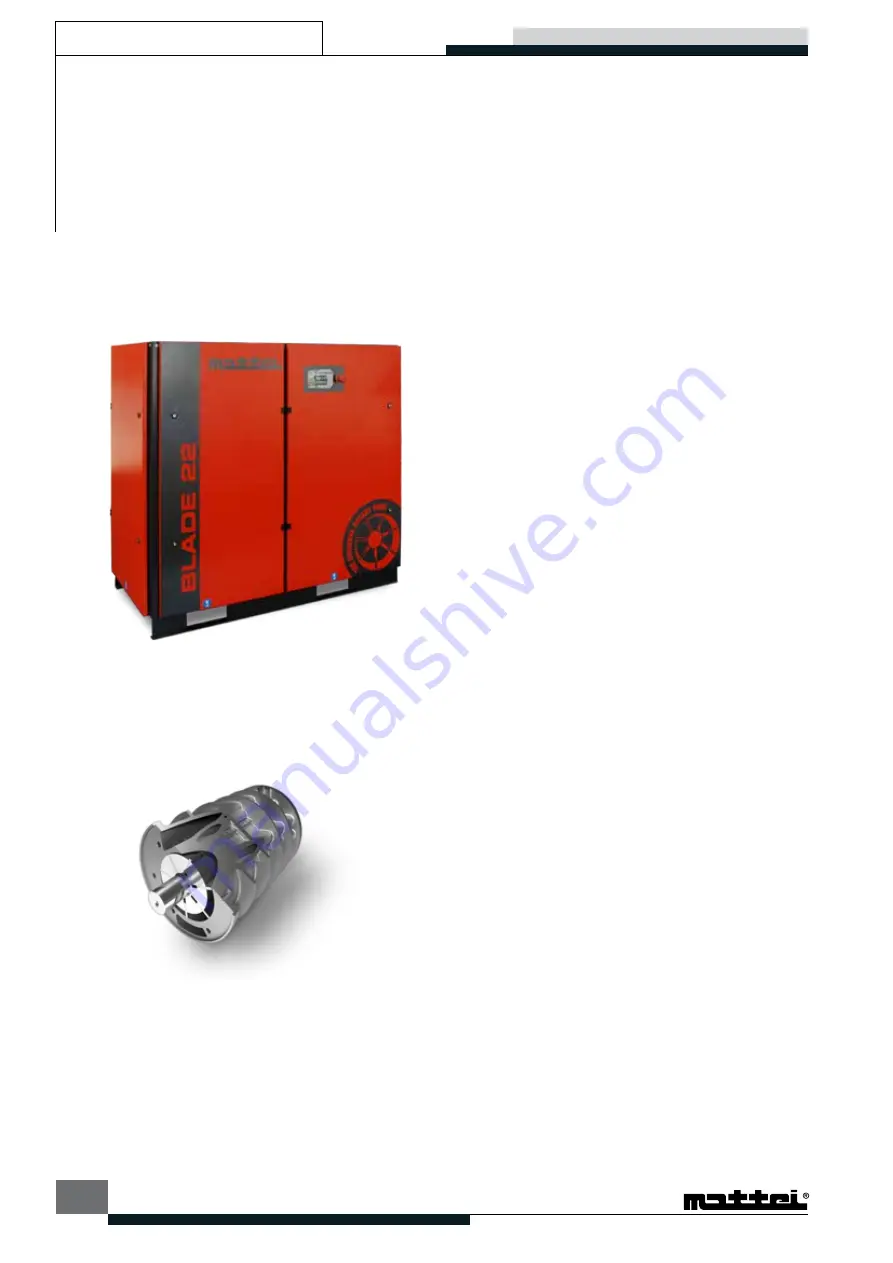
BLADE
3-2
TI215G0010
Description of the machine
All components are eclosed in a soundproofing canopy
in sheet stell, epoxy powder painted and lined with
deadening resistant material. The canopy has a pre-
filter to prevent intake of gross particles that might
prematurely clog the radiators and air filter. Wide
detachable panels and hinged doors allow easy access
for all.
The base has openings to allow easy lifting and handling
of the compressor (See Section 4). Standard packing
includes: fixing on wooden pallets, protective polythene
cover, and a cardboard box.
THE COMpRESSOR
The vane compressor is a volumetric rotary compressor.
It consists of a cylinder (stator) in which a rotor, mounted
eccentrically and tangential with it rotates, and two end
covers.
The rotor has longitudinal slots in which the vanes slide.
The vanes are pushed against the stator by centrifugal
force.
Sealing of the moving parts, cooling and lubrication are
provided by an efficient injection of oil through proper
ports, due to the pressure difference between the
compression chamber and the oil receiver. No pump for
fluid circulation is needed.
An oil film on the inner surface of the stator prevents
direct contact of the moving parts and avoids any
wear. In the vane compressor there are no axial thrusts
pushing the rotor against the end covers. Therefore
there is no need for thrust bearings.
The rotor is supported by white metal bearings having a
practically unlimited lifetime. The air drawn in first passes
through a filter and then through the modulating valve.
The decrease in volume of the pockets formed by the
stator, rotor and vanes produces a continuous, pulse-
free, compression.
INTAKE vALvE
The intake valve, driven by a specific servovalve
through a hydraulic circuit using the same oil as used
for lubrification, adjusts the intake air quantity to the air
system requirements.
MINIMUM pRESSURE AND NON - RETURN vALvE
Compressed air is delivered by the compressor through
a valve ensuring a minimum pressure inside the oil
chamber, so as to guarantee smooth operation when
the compressor is delivering air. This valve also prevents
the compressed air in the system from returning to the
compressor.
OIL SEpARATION
The air/oil separation occurs in different stages and
ensures exceptionally low oil consumptions. The main
mechanical separation occurs in the oil receiver.
This mechanical separation works via the continuous
changes of direction of the air low in the labyrinth path.
The last separation occurs through the coalescing filter,
removing the remaining oil vapours from the air. This
particular oil separation system brings to a very reduced
oil consumption. The large size of the filter and quality
of materials ensure a long life of the filter itself.
MOTOR
The compressor and the motor are connected by means
of exible coupling. This ensures a perfect alignment,
no power absorption, silent operation and no need for
maintenance.
The electric motor is asynchronous, threephase, 4 poles,
with short circuit winding.


