81
10.5 TV BRACKET INSTALLATION - CONTINUED
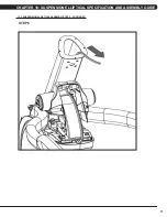
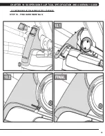
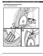
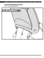
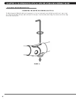
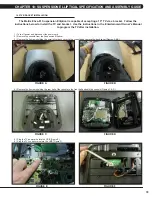
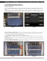
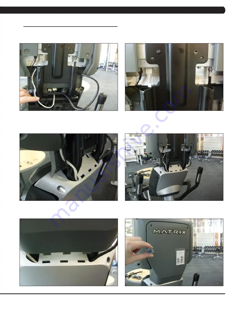
12) Route the TV power, controller, and console cables out the back of the console and plug into the back of the TV (Figures M & N).
13) The new TV should now be programmed and thoroughly tested before installing the covers. See Section 8.11 for TV troubleshooting help
if needed.
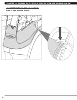
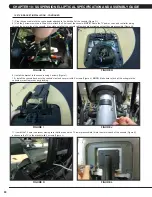
14) Install the console back cover onto the console.
NOTE:
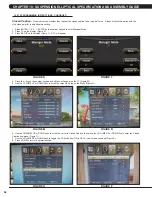
You will need to push the top end of the back cover beneath the TV lower plastic
cover and route the wiring through the hole in the back cover (Figure O). Once you have the top of the back cover in position, push the lower
part of the back cover into position. It should snap into place (Figure P).
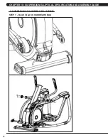
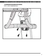
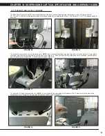
15) Install the TV back cover onto the unit.
NOTE:
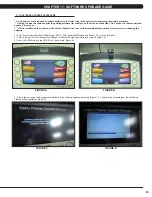
You will need to line up the tabs at the bottom of the TV back cover to the slots in the
console back cover (Figure Q). Secure the TV back cover with 4 screws (Figure R).
FIGURE R
FIGURE Q
FIGURE P
FIGURE O
FIGURE N
FIGURE M
CHAPTER 10: SUSPENSION ELLIPTICAL SPECIFICATION AND ASSEMBLY GUIDE
Summary of Contents for E3XE - 01
Page 1: ...E 3 X E 0 1 S U S P E N S I O N E L L I P T I C A L S E R V I C E M A N U A L...
Page 4: ...1 1 1 SERIAL NUMBER LOCATION CHAPTER 1 SERIAL NUMBER LOCATION SERIAL NUMBER LOCATION...
Page 26: ...23 8 1 ELECTRICAL DIAGRAMS CHAPTER 8 TROUBLESHOOTING...
Page 27: ...24 CHAPTER 8 TROUBLESHOOTING 8 1 ELECTRICAL DIAGRAMS CONTINUED P21 DIGITAL COMMUNICATION WIRE...
Page 28: ...25 8 1 ELECTRICAL DIAGRAMS CONTINUED CHAPTER 8 TROUBLESHOOTING G14 HAND PULSE CONNECTING WIRE...
Page 90: ...87 NOTES...

