57
CHAPTER 9: PART REPLACEMENT GUIDE
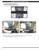
9.15 PEDAL ARM REPLACEMENT
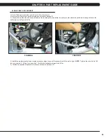
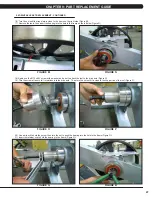
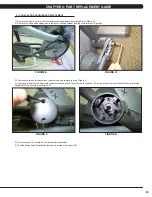
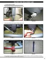
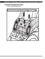
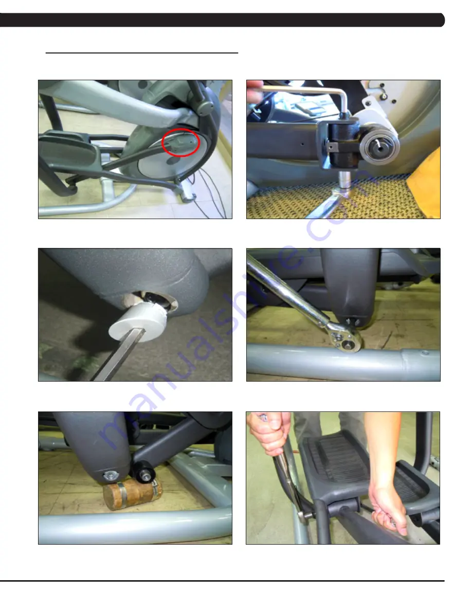
1) Remove the plastic cover where the pedal arm attaches to the crank (Figure A).
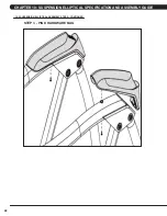
2) Disconnect the pedal arm from the crank (Figure B).
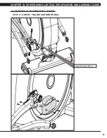
3) Remove the plastic cap from the swing arm (Figure C).
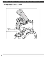
4) Remove the bolt that holds the pedal and swing arms together (Figure D).
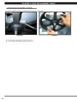
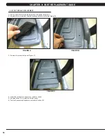
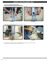
5) The swing arm can now be separate from the pedal arm (Figure E).
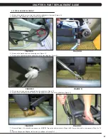
6) Remove the bolt that holds the link arm to the pedal arm and remove the pedal arm (Figure F).
7) Reverse Steps 1-5 to install a new pedal arm.
NOTE:
Torque the bolt removed in Step 4 to 80 N-m and the bolt / nut removed in Step 2 to 70
N-m. .
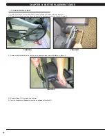
8) Test the Suspension Elliptical for function as outlined in Section 9.21.
FIGURE A
FIGURE B
FIGURE C
FIGURE D
FIGURE E
FIGURE F
Summary of Contents for E3XE - 01
Page 1: ...E 3 X E 0 1 S U S P E N S I O N E L L I P T I C A L S E R V I C E M A N U A L...
Page 4: ...1 1 1 SERIAL NUMBER LOCATION CHAPTER 1 SERIAL NUMBER LOCATION SERIAL NUMBER LOCATION...
Page 26: ...23 8 1 ELECTRICAL DIAGRAMS CHAPTER 8 TROUBLESHOOTING...
Page 27: ...24 CHAPTER 8 TROUBLESHOOTING 8 1 ELECTRICAL DIAGRAMS CONTINUED P21 DIGITAL COMMUNICATION WIRE...
Page 28: ...25 8 1 ELECTRICAL DIAGRAMS CONTINUED CHAPTER 8 TROUBLESHOOTING G14 HAND PULSE CONNECTING WIRE...
Page 90: ...87 NOTES...

