80
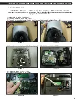
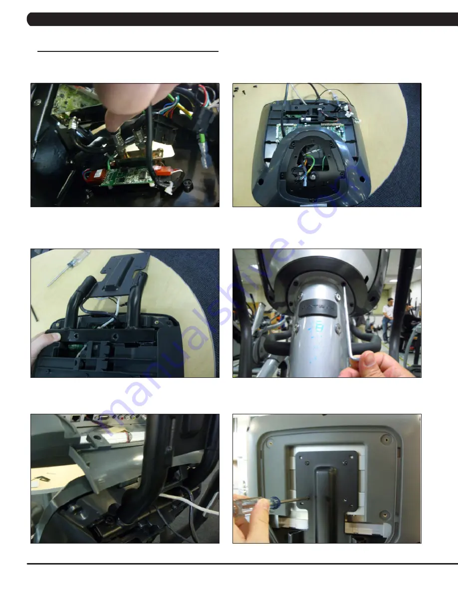
7) Plug the coax cable into the coax adaptor attached to the back half of the console (Figure G).
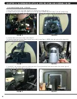
8) Use the 4 screws removed in Step 4 to re-attach the 2 halves of the console.
NOTE:
Route the TV power, coax, and controller wiring
through the hole in top of the console. Also make sure that the console cable wires are protruding so that they are accessible (Figure H).
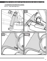
9) Install the bracket to the console using 4 screws (Figure I).
10) Install the console back onto the console mast and secure it with 5 screws (Figure J).
NOTE:
Make sure to tuck all the wiring into the
console or mast to prevent any pinching.
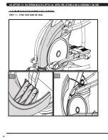
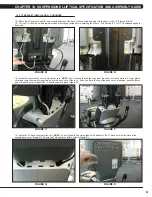
11) Install the TV onto the bracket making sure that the tabs on the TV lower plastic shield fit into the slots in back of the console (Figure K),
and secure the TV to the bracket with 4 screws (Figure L).
10.5 TV BRACKET INSTALLATION - CONTINUED
FIGURE L
FIGURE K
FIGURE J
FIGURE I
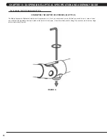
FIGURE H
FIGURE G
CHAPTER 10: SUSPENSION ELLIPTICAL SPECIFICATION AND ASSEMBLY GUIDE
Summary of Contents for E3XE - 01
Page 1: ...E 3 X E 0 1 S U S P E N S I O N E L L I P T I C A L S E R V I C E M A N U A L...
Page 4: ...1 1 1 SERIAL NUMBER LOCATION CHAPTER 1 SERIAL NUMBER LOCATION SERIAL NUMBER LOCATION...
Page 26: ...23 8 1 ELECTRICAL DIAGRAMS CHAPTER 8 TROUBLESHOOTING...
Page 27: ...24 CHAPTER 8 TROUBLESHOOTING 8 1 ELECTRICAL DIAGRAMS CONTINUED P21 DIGITAL COMMUNICATION WIRE...
Page 28: ...25 8 1 ELECTRICAL DIAGRAMS CONTINUED CHAPTER 8 TROUBLESHOOTING G14 HAND PULSE CONNECTING WIRE...
Page 90: ...87 NOTES...

