37
CHAPTER 9: PART REPLACEMENT GUIDE
9.2 FRONT SHROUD REPLACEMENT - CONTINUED
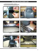
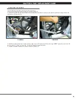
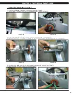
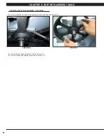
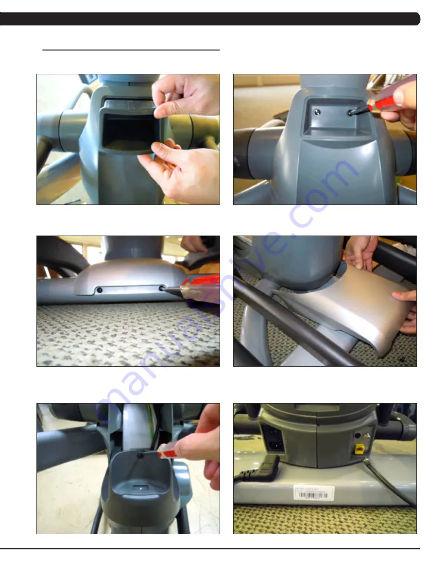
7) Pull out the rubber tray from the cup holder plastic (figure G).
8) Remove the 2 screws to disassemble the cup holder plastic and remove it from the unit (Figure H).
9) Remove the 2 screws to disassemble and remove the middle stabilizer sweat cover (Figures I & J).
10) Remove the 1 screw (exposed when the cup holder is removed) holding the orange slot cover to the frame and remove it (Figure K).
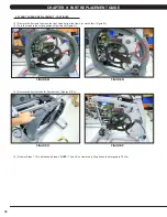
11) Remove all of the cables from the front shrouds (Figure L).
FIGURE L
FIGURE J
FIGURE H
FIGURE K
FIGURE I
FIGURE G
Summary of Contents for E3XE - 01
Page 1: ...E 3 X E 0 1 S U S P E N S I O N E L L I P T I C A L S E R V I C E M A N U A L...
Page 4: ...1 1 1 SERIAL NUMBER LOCATION CHAPTER 1 SERIAL NUMBER LOCATION SERIAL NUMBER LOCATION...
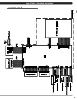
Page 26: ...23 8 1 ELECTRICAL DIAGRAMS CHAPTER 8 TROUBLESHOOTING...
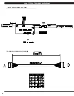
Page 27: ...24 CHAPTER 8 TROUBLESHOOTING 8 1 ELECTRICAL DIAGRAMS CONTINUED P21 DIGITAL COMMUNICATION WIRE...
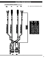
Page 28: ...25 8 1 ELECTRICAL DIAGRAMS CONTINUED CHAPTER 8 TROUBLESHOOTING G14 HAND PULSE CONNECTING WIRE...
Page 90: ...87 NOTES...

