background image

Mass Sine Ultra 

– Installation Manual Multiple Units 


17


6  TROUBLESHOOTING 

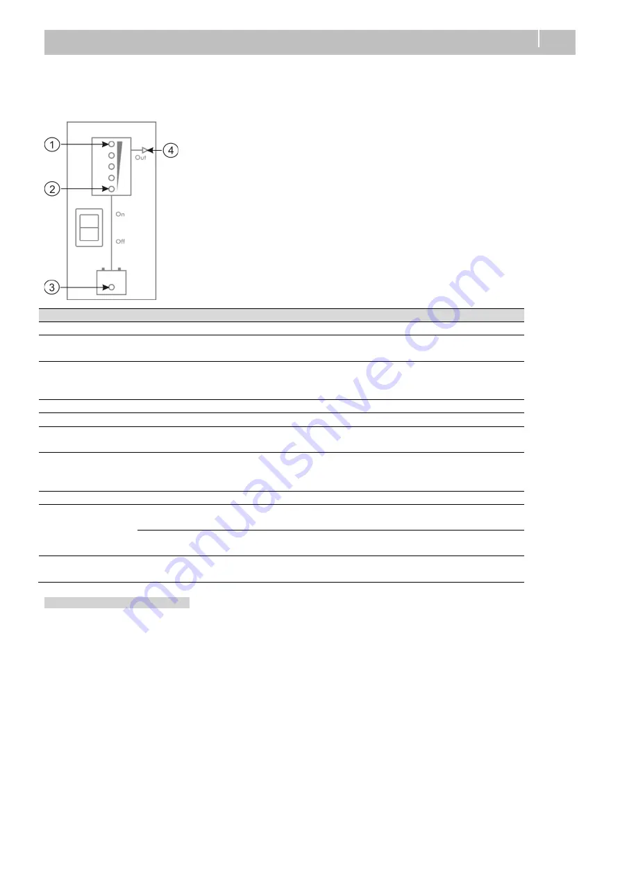
Errors in parallel configuration will be shown by the LED indicators in the display. 

Note: 

An error also occurs if the AC OUT of the units are not connected to each other (breakers!). 


Illuminating LEDs 

MasterBus alarm 

Explanation / Possible cause 

What to do 

Normal operation and warnings 

None 


The Mass Sine Ultra is 
switched off manually. 

Switch on the Mass Sine Ultra by 
means of the main switch. 

(1) red 

MB monitoring: 
Overload 

Inverter in overload, inverter 
exceeds max continuous 
power. 

Check the load connected. Check 
the connections. 

(3) red 

Battery low/high 

Battery voltage low/high. 

Stop inverting 

Errors (Mass Sine Ultra shuts down) 

(1) and (3) red, 
(2) yellow 

Over temperature 

Mass Sine Ultra too hot. 
Restart when alarm is over. 

Check ventilation. Reduce load. 

(1) and (3) red 

System error,  
Sync error,  
Config error 

Communication disturbed.  
Configuration wrong. 

Check communication cables and 
connectors 

Permanent errors (manual reset required) 

(1) and (3) blinking 
fast red 

Overload 

Number of inverter overload 
restart attempts exceeded. 

Reduce the output loads, shut 
the Mass Sine Ultra Off and On.  

System error 

Hardware issue. 

Shut the Mass Sine Ultra Off and 
On. 

(4) blinking fast 

Install error 

Installation error. 

Correct installation, shut the 
Mass Sine Ultra Off and On. 


Monitoring a three-phase cluster 

In MasterAdjust, on the monitoring tab of the L1 unit, first the data for the unit itself is shown. Next are the Cluster groups (L1, 
L2 and L3). Per phase, input and output data is shown. If more units are clustered per phase, their values are combined. 

The list with AC outputs shows the values for the selected unit. 


Summary of Contents for MASS SINE ULTRA

Page 1: ...MULTIPLE UNITS MASS SINE ULTRA Parallel or three phase configurations INSTALLATION MANUAL 10000019321 00...

Page 2: ...iring of parallel units 7 3 6 Configuration with MasterAdjust 7 3 7 Initial start up 9 4 PARALLEL CONFIGURATION WITH DIP SWITHES 10 4 1 Materials needed 10 4 2 Preparation 10 4 3 DC wiring of parallel...

Page 3: ...can be made available 1 4 General installation guidelines When using units in a multiple unit configuration the following requirements are applicable in addition to the requirements mentioned in the...

Page 4: ...the 3 phase with MasterAdjust installation procedure Start 3 Phase More than 2 units Lithium Ion Batteries Click here or go to page 5 for the parallel with MasterAdjust installation procedure YES Para...

Page 5: ...es to interconnect all units product code e g 3 meter 6502000030 n 1 MasterBus USB Interface product code 77030100 1 Windows based PC with the MasterAdjust configuration tool 1 DC cable with fuse n DC...

Page 6: ...ection Inline fuse Recommended battery bank Indicated cable sizes are for cables from unit to busbar and shorter than 3m Cables from busbar to battery bank should be twice the diameter When cables are...

Page 7: ...left pane of MasterAdjust right click the Primary unit and select Login The Primary unit is the device that has the AC OUT 2 connection The other units are called Replica units Note that in the older...

Page 8: ...y Replica 15 Click the Select devices button to be able to select the Replica unit s 16 Notice the Cluster topology and Cluster state Topology monitors the size of the cluster whether the selected num...

Page 9: ...ne of MasterAdjust the Replica unit s will now be listed under the Primary unit 3 7 Initial start up 1 Switch all units off and on again 2 Check that the units are working as inverter 3 Close the AC b...

Page 10: ...e 2 AC cable to connect the AC input of the unit to an external power source MSU 2 AC cable to connect the external load to OUT 2 4 2 Preparation Make sure that all power sources AC and DC are switche...

Page 11: ...are switched off 2 Make sure that all connections are firmly tightened Configuration 3 Use a small screwdriver to carefully set the DIP switches of block A DIP switch location Circuit Breaker no RCD R...

Page 12: ...position 0 and set 2 on position 1 All other DIP switches 3 8 on the Replica unit must match the settings on the Primary unit For an overview of DIP switch settings please see the user manual 4 7 Init...

Page 13: ...ble to connect the external load to OUT 3 5 2 Preparations Make sure that all power sources AC and DC are switched off Make sure that DIP switches A1 and A2 are off on all units DIP switch location Al...

Page 14: ...onnect a MasterBus USB Interface to the MasterBus network and to a PC and open MasterAdjust Installation or configuration errors may come up in MasterAdjust while the configuration is in progress This...

Page 15: ...for example must be configured for ALL units separately 12 In the Cluster pane from the Phase System drop down list select Three Phase You may need to maximize the MasterAdjust window or scroll all th...

Page 16: ...ual to the selected number of devices State monitors the configuration state of the cluster Click the Activate cluster button to finish the cluster configuration The Cluster state will change from Inc...

Page 17: ...erature Mass Sine Ultra too hot Restart when alarm is over Check ventilation Reduce load 1 and 3 red System error Sync error Config error Communication disturbed Configuration wrong Check communicatio...

Page 18: ...Shipping Advanced Systems Group US N85 W12545 Westbrook Crossing Menomonee Falls Wisconsin 53051 United States Asia Pacific Customer Service T 64 9 415 7261 Option 1 E enquiries bepmarine com Technica...

Reviews: