Paragraphs
226-227
nect pressure line at Multi-Power/ipto
pump if so equipped. Support t.ransmis·
sion housing and differential separate·
ly, remove retaining bolts and separate
rear of tractor from transmission hous·
ing. Remove pump mounting dowels
(P-Fig. 228) from each side of difTeren·
tial housing. Disconnect hydraulic pipes
from the pumps and remove tube and
spring from pump servo valve (10-Fig.
237). Slide pump assembly forward
through front opening of differential
housing.
The gear train mounting plates
(5
and
14-Fig. 236) serve as pump support.
Idler gear (9) contains 22 loose needle
bearings (10). Gear backlash is not ad·
justable; renew parts as necessary if
backlash exceeds 0.38 mm (0.015 inch)
between any two gears.
To reinstall pump assembly, reverse
the removal
procedure.
226. OVERHAUL. To disassemble
the removed hydraulic pump, first
separate the auxiliary pump and drive
train from main pump. Turn pressure
control adjusting screw (1-Fig. 238) out
of pivot lever (2) until end of bolt is flush
with inside of lever. Remove adjusting
block (13), tube (14) and spring (15) from
servo valve if not removed previously.
Unhook diaphragm lever link (4) from
control valve, remove valve mounting
stud nut, and remove servo valve from
top of pump.
Remove clip retaining control lever
(1-Fig. 237), then slide control lever
from control valve (28). Remove rollers
and pin from end of control valve ac·
tuating rod. Remove filter assembly and
intake housing
(5)
from pump.
Remove retainer clip and cap (24) from
front of oscillator cU.·ive. Remove pin re·
taining oscillator (25) to cam follower
(20). Remove nuts attaching pump
bodies together, then carefully remove
front body (22). Withdraw control valve
and oscillator as a unit from pump.
Carefully slide piston yokes (14), valve
chambers (19), cam blocks (16 and 21)
and camshaft (18) away from rear body
(11). Pull valve spool sleeve from rear
body.
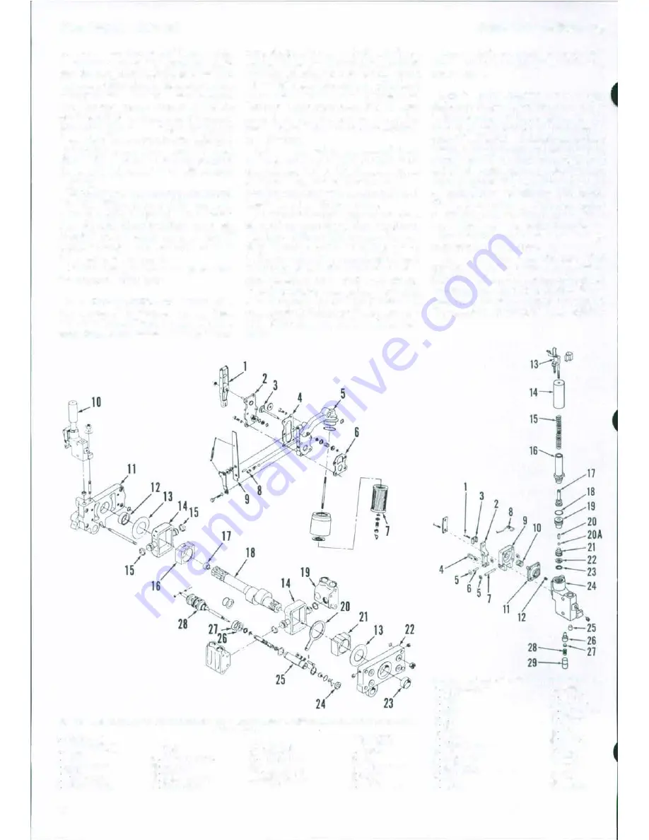
Fig. 237-E'IIploded view of main hydraulic pump. Thrust washers (13) are not used on early produc·
I
Control lever
2. Rear cover pletAl
3 Nooreturn \'o1ve
4 GMket
5 lnteke housing
6 GOAket
7 F1l�r olement
8 Onnc:e bushing
88
9. Response control
lever
10 Servo valve
11M)'
11 Rear body
12 Buslung
IS
Thru4t
wuhero
14 PiMu>n
yoke•
tlon pumps.
15.
Ploton rings
16. Com block
17 Needle bearing
18. Cemshaft
19. Valve chamber
20. Oecillator drive
(cam followorl
21. Cam block
22. Front
body
23 Bu&hing
24
Nut
26. Oscillotor
8118}'.
26 Waeher
27 Spacer
28 Control valvo
all8)'.
MASSEY -FERGUSON
Disassemble the removed assemblies
as outlined in the appropriate following
paragraphs.
227. SERVO VALVE. Refer to Fig.
238 for exploded view of servo valve. Un·
bolt and remove diaphragm cover (9).
Use an Allen wrench to remove orifice
plug (12). Thread a suitable screw into
retainer plug (29) and remove retainer,
spring (28), discs (27) and secondary
relief valve (26). Remove guide (16) and
spring support (17), then bump housing
to remove plunger (20) and ball (20A).
Use hooked wire to pull plunger guide
(19) from bore then
use
needlenose pliers
to pull ball valve seat. (21) from bore.
Inspect all parts for wear or damage
and renew as necessary.
Diameter of large end of plunger (20)
should
be
5.530·5.542 mm (0.2177-
0.2182
inch), and diameter
of
tapered
end of plunger should
be
5.080·5.232 mm
(0.200·0.206 inch). Bore of plunger guide
(19) should be 5.644-5.669 mm (0.2222·
Fig. 238-E'IIploded view of servo valve assembly.
I
AJijusting BCrew
16.
Guide
2 Lever
17
Support
3 Chp
18.
"0" rina
4 Lmk
19 Plunger
IIUid•
6 Clip
20
Plu"'l"r
6 Pon
20A. Ball
1 P,n
21 Seat
8 Sprins
22 W aahor
9 D•ophragm cover
23. "0" nng
10 Sprong
24. Body
1 1
Dlophl'llgm
25. Dowol
12
Orifice
plug
26. Valve
13 Block
OS8y.
27.
01oc
I� Head
28. Sprlnll
15 Spring
211.
Retainer


