SERVICE MANUAL
Move transmission input shaft forward
slightly and remove spacer plate
Cl7l.
Withdraw input shaft rearward from
transmission case while sliding clutch
assembly
<251
and overdrive pinion
<231
off the shaft. Inspect net>dle bearing
(20),
sealing rings
(2ll
and input shaft
for
wear or damage and renew 1f necessary.
Th
disassemble the remo,·ed Multi
Power clutch unit, place clutch assembly
on a clean bench with ove1·drive pinion
(1-
Fig.
151l
up. Push down on clutch
retainer plate
(3)
to compress return
springs, then remove snap ring
(2)
with
a narrow blade screwdriver. Remove all
components from clutch housing
(10)
and
examine for wear, scoring or other
damage. Renew clutch sealing rings
(8
and
9)
whenever clutch is disassembled.
Renew any components that show
signs of wear, damage, distortion or
overheating. Thickness of friction discs
(4)
when new is
2.41-2.59
mm
(0.095-0.102
inch). Thickness of driving
plates
(5)
when new is
1.67-1.75
mm
(0.660-0.690
inch). Fnction discs and
drive plates must be renewed as a
com
plete set.
When reinstalling piston
(7),
careful
ly compress outer seal ring
(8l
using a
feeler gage blade or similar tool while
working piston into clutch housing.
When assembling clutch plates, note
that clutch housing contains six bleed
holes (B-Fig.
152)
that are evenly spac
ed around the housing and that drive
p
l
ates have six external lugs. Install first
drive plate on lop ofpist.on with lugs
(L)
located one spline
t.o
the right (clockwise)
from bleed holes. Place the
six
piston
return springs on the lugs of the first
drive plate. Install friction discs and re
maining two drive plates alternately,
staggering the lugs of each plate one
spline further to the right. of the plate
previously installed as shown in Fig.
152.
Make certain that. return spr·ings
contact only the fir·st. plate, then install
retainer (3-Fig.
151)
and snap ring
(2).
Fig.
152-Cross-sectlonal view
of Multi-Power
clutch showing recommended method of
as
..
mbly.
Refer
to text.
8
Bleed
h
ole
L
Urove
I
URI on
tlutch
0
Clutch dii'C•
pl•t�•
To
reinstall clutch unit and input
shaft, reverse the removal procedure.
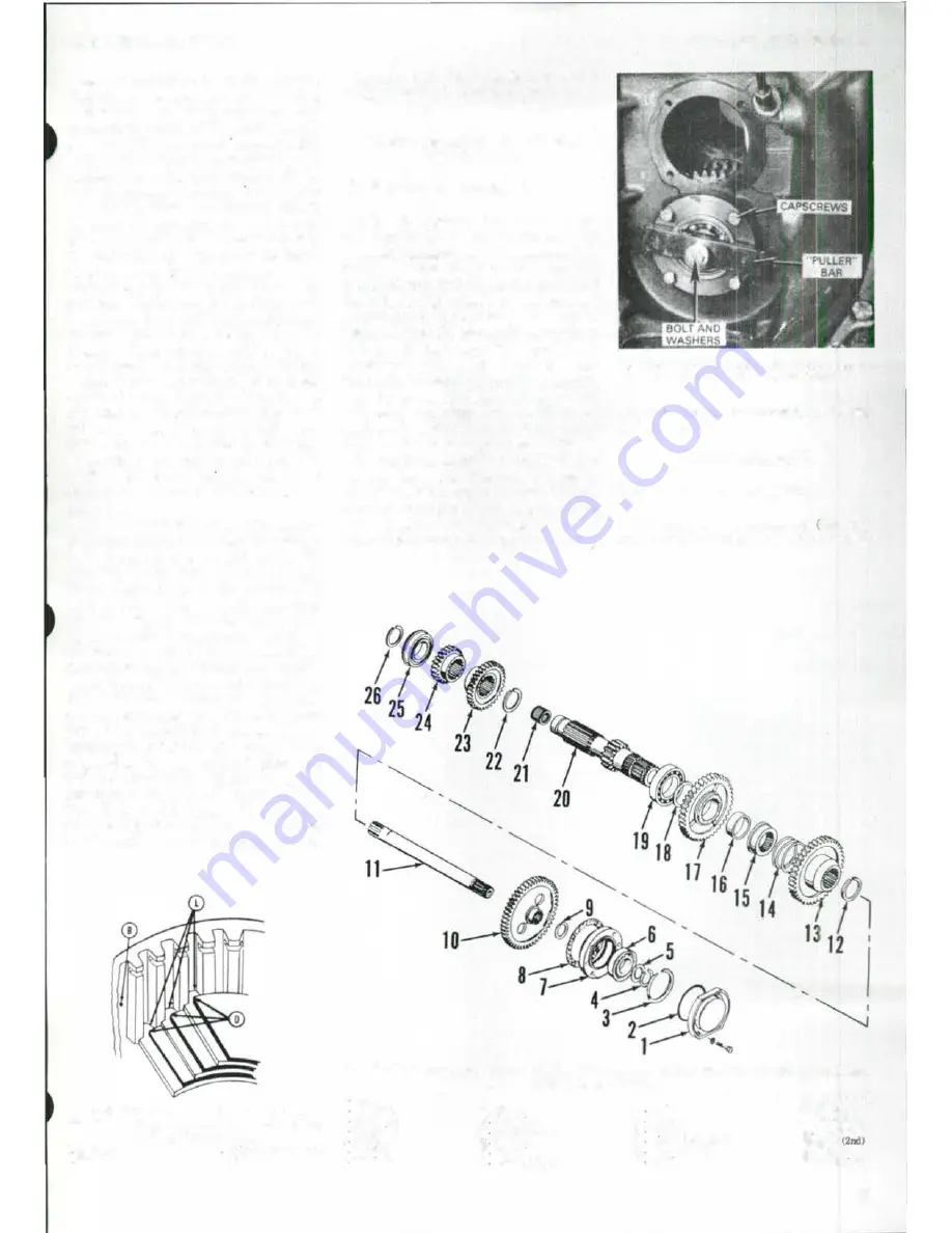
PTO LOWER SHAFT AND
DRIVE GEAR
All Models So Equipped
155.
To
remove plo lower shaft
(11
-Fig
. 153),
first
remove transmission
assembly
as
outlined in paragraph
145.
Remove clutch throwout bearing, fork
and shaft and the brake pedal
cross
shaft
from front of pto shaft. Thread two cap
screws into tapped holes in bearing re
tainer
(7)
and tighten evenly to
force
re
tainer with bearing off front of shaft.
Withdraw pto shaft rearward from
transmission housing.
Pto
drive gear
(10)
can be removed from housing after
removing mainshaft as outlined in
paragraph
152
and transmission input
shaft as outlined in paragraph
154.
To
reinstall, reverse the removal pro·
cedure. Front end of pto shaft contains
a
threaded hole that can be
used to pull
shaft into front bearing as shown in Fig.
154.
Apply nonhardening sealer to
threads of retainer and cover mounting
Paragraphs
1 55-156
Fig.
1
5
4
-
P
t
o
lower shaft
Is drll/ed and tapped at
front end for Installation
u
shown.
cap screws, then tighten to
60
>J
·
m
(45
l't.-lbs.l torque.
COUNTERSHAFT
All Models So Equipped
156.
1b
remove countershaft. 20-Fig.
153),
first
remove transmission assembly
Fig. 153-Exploded view of lower
pro shaft and trantmlsslon countershalt with associated parts used
In Mu/11-Power transmission.
I
Cover
2
"0"
ring
3
Snap ring
4
Snap
nng
6 Woeher
6
Beanng
7
Re1.81ner
8. Goakel
9
Snap
nng
10 PI<> clnve
gear
II PI<>
lower
ohoJ\
12 Snap
nn11
13
Overdrive gear
14
Spnn11
16
Coupler
16
Bushing
17
Direct
d
r
i
v
e
gear
18
Thruat
wuher
19
Re8rlng
20. Count.oraiW\
21. Beanna
22. Snap
ring
23 Gear
13rcll
24.
Gear
25. Bearlna
26.
Snap nng
63


