background image

SAFETY INSTRUCTIONS 

SAVE THESE INSTRUCTIONS. This manual contains important instructions that should be 
followed during installation and maintenance of the UPS and batteries. 

The  UPS  models that are covered in this manual are intended for installation in an 
environment within 0 to 50°C, free of conductive contaminant. 
 
WARNING: This is a product for commercial and industrial application in the second 
environment – installation restrictions or additional measures may be needed to prevent 
disturbances. 


Certification standards 

• 

Safety: EN 62040-1 

• 

EMC: IEC/EN 62040-2   

• 

Performance: IEC/EN 62040-3   

Special symbols 

The following are examples of symbols used on the UPS or accessories to alert you to 
important information: 


RISK OF ELECTRIC SHOCK

 - Observe the warning associated with the risk of electric shock 

symbol. 
 
Important instructions that must always be followed. 
 
Do not discard the UPS or the UPS batteries in the trash. 
This product contains sealed lead acid batteries and must be disposed as it's explain in 
this manual. For more information, contact your local recycling/reuse or hazardous 
waste center. 

This symbol indicates that you should not discard waste electrical or  electronic 
equipment (WEEE) in the trash. For proper disposal, contact your local recycling/reuse 
or hazardous waste center. 

 
Information, advice, help. 

 
Refer to the user manual. 


Summary of Contents for Tacoma II Series

Page 1: ...0 Kaplan Ave City of Industry CA 91744 U S A Tel 1 714 870 6888 Fax 1 714 870 4888 Toll Free 1 888 MARUSON E Mail Info MarusonUSA com Website www MarusonUSA com All trademarks are the property of their respective owners Product specifications are subject to change without prior notice ...

Page 2: ...ance IEC EN 62040 3 Special symbols The following are examples of symbols used on the UPS or accessories to alert you to important information RISK OF ELECTRIC SHOCK Observe the warning associated with the risk of electric shock symbol Important instructions that must always be followed Do not discard the UPS or the UPS batteries in the trash This product contains sealed lead acid batteries and mu...

Page 3: ...ling Wear rubber gloves and boots Do not lay tools or metal parts on top of batteries Disconnect charging source prior to connecting or disconnecting battery terminals Determine if battery is inadvertently grounded If inadvertently grounded remove source from ground Contact with any part of a grounded battery can result in electrical shock The likelihood of such shock can be reduced if such ground...

Page 4: ...t If the system must be stored prior to installation storage must be in a dry place The admissible storage temperature range is 25 C to 60 C with battery 15 C to 40 C without battery Special precautions The unit is heavy wear safety shoes and use vacuum lifter preferentially for handling operations All handling operations will require at least two people unpacking lifting installation Before and a...

Page 5: ...SIGNAL CABLE 22 4 3 PARALLEL SYSTEM OPERATION 22 5 OPERATION 23 5 1 CONTROL PANEL 23 5 2 LCD DESCRIPTION 25 5 3 DISPLAY FUNCTIONS 27 5 4 USER SETTINGS 28 5 5 UPS STARTUP AND SHUTDOWN 29 5 6 LCD OPERATION 30 6 COMMUNICATION 39 6 1 COMMUNICATION PORTS 39 6 2 INTELLIGENT CARD OPTIONAL 40 6 3 UPS MANAGEMENT SOFTWARE 40 7 UPS MAINTENANCE 41 7 1 EQUIPMENT CARE 41 7 2 TRANSPORTING THE UPS 41 7 3 STORING ...

Page 6: ...e materials Dismantling and destruction must take place in compliance with all local regulations concerning waste At the end of its service life the product must be transported to a processing center for electrical and electronic waste Battery The product contains lead acid batteries that must be processed according to applicable local regulations concerning batteries The battery may be removed to...

Page 7: ...ower density utility frequency independence and generator compatibility Selectable High Efficiency mode of operation Standard communication options one RS232 communication port one USB communication port one dry in port and dry out port Optional connectivity cards with enhanced communication capabilities Firmware that is easily upgradable without a service call ...

Page 8: ...ult Product Model Name Net Weights kg Unit Size W x H x D mm Remark UPS Tacoma Tower LV 6K 99 6 300 805 5 633 2 16 batteries 7AH Tacoma Tower LV 10K 122 2 16 batteries 9AH Tacoma Tower LV 6K BT 20 108 4 300 805 5 633 2 20 batteries 7AH Tacoma Tower LV 10K BT20 123 8 20 batteries 9AH EBM Tacoma T EBM 94 5 225 589 416 16 2 batteries 9AH Type Description Remark Intelligent Card Dry Contact card AS400...

Page 9: ...on UPS modular Front view 1 Ventilation area 2 LCD Modular including 2 1 Button 2 2 LCD screen 2 3 LED indicator Rear view 6K 10K 1 Intelligent Slot optional default is no card inside only cover and inside cable 2 USB ...

Page 10: ...arallel Port optional default is no card inside only cover and inside cable 7 DRY IN OUT 8 Input Output terminal 9 Input Circuit Breaker 10 External battery connector 11 Maintenance bypass switch optional default is Yes EBM External Battery Modular Front view 1 Ventilation area 2 EBM label ...

Page 11: ...11 Rear view 1 EBM port 1 2 EBM port 2 3 Fuse board cover replace EBM fuse 2 3 Circuit diagram ...

Page 12: ...the unit are absolutely dry hazard of electric shock If any equipment has been damaged during shipment keep the shipping cartons and packing materials for the carrier or place of purchase and file a claim for shipping damage If you discover damage after acceptance file a claim for concealed damage Tower UPS Tower EBM Note The cabinet is heavy please see spec weight provided on the carton label Do ...

Page 13: ... O Option default is Not configured Assembled to Unit as accessory 3 3 Mechanical Install To keep air flowing freely it is recommended to keep a clearance with 500mm space both for front and rear side UPS model 1 Place the unit on a flat surface in its final location and install Tower foot for a stability 2 Install the unit to ground Option place 4pcs bolts M8 is recommended to the final location ...

Page 14: ... to wiring AC IN OUT cable to UPS in difference mode and UPS connecting with EBM 3 4 1 Input Output wiring specifications Recommended protective devices and cable cross sections Recommended upstream protection UPS power rating Upstream circuit breaker 6000VA D curve 63A 10000VA D curve 100A to UPS Normal AC Bypass AC source G N L2 L1 Read the Safety instructions page 3 regarding backfeed protectio...

Page 15: ...rallel system 6mm 2 8AWG 75 C type 16mm 2 4AWG 75 C type It is recommended that an external isolating device should be installed between the mains input and UPS as shown in Figure AC Contactor 208 240V 63A 6 kVA 208 240V 100A 10 kVA 3 4 2 Wiring for AC Cable AC source to UPS High leakage current Earth connection essential before connecting supply Common input output sources connection This type of...

Page 16: ... TB L1 L2 N1 N2 PE is screw 3 PARA JUMPER For UPS s parallel installation JP1 JP2 Below will introduce 3 modes Default is LV mode 1 of wiring application for UPS input output please select one mode for your actual application LV mode 1 Short UPS output terminal L1 L2 and N1 N2 with busbar then connect AC cable ...

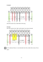
Page 17: ... Each 120V output only can take half an UPS rating HV mode Short UPS input terminal L2 N1 with busbar then connect AC cable For the cable well fixed it is recommended to tie these cables to the convex of rear panel ...

Page 18: ...ke sure that the number of battery sections and capacity are the same as LCD setting 4 Do not reverse the polarity of the external battery Connect with user s own EBM Connect EBM to UPS with Battery cable optional configured Note 1 If additional battery cable needed for installation it must follow cable specification and the maximum length of battery cable 10 meters for application 2 If a length o...

Page 19: ...19 Connect with the configured EBM Note 1 Extended runtime with up to 6 Extended Battery Modules EBMs per UPS 2 Extend more than 2 EBMs additional ground wires 10mm 2 cross sectional area are require ...

Page 20: ...distance between the load and the parallel UPS is less than 10 meters the length difference between the input output lines between the UPSs in the parallel system is less than 20 When the distance between the load and the parallel UPS is greater than 20 meters the length difference between the input output lines between the UPSs in the parallel system is less than 5 2 In the parallel system common...

Page 21: ...21 LV mode 2 HV mode When 3 UPSs in parallel JP1 JP2 wiring as below ...

Page 22: ...l start to turn on and enter line mode 3 Regulate the output voltage of the each UPS separately and check if the output voltage difference between the two ups is less than 0 5V If the difference is more than 0 5V the UPS need to be regulated 4 If the difference output voltage is less than 0 5V turn off the input breakers to let UPS shut down Then switch on the output breakers for the two UPS 5 Tur...

Page 23: ...ts and settings The following table shows the indicator status and description Indicator Status Description Normal Green On The UPS is operating normally on Online or on High Efficiency mode Battery Orange On The UPS is on Battery mode Bypass Orange On The UPS is on Bypass mode Flash The UPS is on Standby mode Fault Red On The UPS has an active alarm or fault ...

Page 24: ... 100ms 1s to scroll down the menu option Enter next menu tree Press this button for 100ms 1s to select the present menu option or enter next menu but do not change any setting Select one menu option Press this button for 100ms 1s to select the present menu option or enter next menu but do not change any setting Confirm the present setting Press this button for 1s to confirm the edited options and ...

Page 25: ...very second Bypass output Beep every 2 minutes 5 2 LCD description The LCD backlight automatically dims after 2 minutes of inactivity except UPS is fault Press any button to wake up the screen The following table describes the information of ups status Note If other indicator appears see troubleshooting on chapter 7 2 for more information Operation status Cause Description Standby mode The UPS is ...

Page 26: ...cy mode Once the mains are loss or abnormal the UPS would transfer to Line mode or Battery mode and the load is supplied continuously 1 The function could be enabled through the LCD setting or the software Winpower etc 2 It is reminded that the transfer time of UPS output from HE mode to battery mode is about 10ms But it is still too long for some sensitive load Bypass mode Overload or fault has o...

Page 27: ...executing a battery test Test the battery Battery fail The UPS detects bad battery or battery disconnected The symbol of battery failure would be shown and UPS would alarm UPS Parallel Using two or three UPS for heavy load or redundancy Two or three UPS operation in parallel 5 3 Display functions Use the two middle buttons and to scroll through the menu structure Press the Enter button to select a...

Page 28: ...ent list Identification Product type model Part Serial number UPS NMC firmware 5 4 User settings The following table displays the options that can be changed by the user Submenu Available settings Default settings Password Key the password USER language English Deutsch Español English User password disabled Enabled disabled Audible alarm enabled disabled enabled Output voltage 208V 220V 230V 240V ...

Page 29: ...startup and shutdown Please make sure there is no load connected to the ups before the ups is turned on and take on the load one by one after the UPS is turned on Take off all of the connected loads before turning off the UPS Starting the UPS with utility Verify that the total equipment ratings do not exceed the UPS capacity to prevent an overload alarm Start the UPS with utility Check all the con...

Page 30: ...shutdown with utility To shut down the UPS with utility Pressing button continuously for more than 3 seconds and the buzzer will beep 300ms After that the UPS will turn into Bypass mode at once When completing the above action UPS output voltage is still present In order to cut off the UPS output simply cut off the utility power supply A few seconds later the ups will shut down and no output volta...

Page 31: ...ation about alarm battery the system status would be shown In the default UPS status summary screen when pressing ESC 300ms the display would enter main menu tree The main menu tree includes six branches UPS status menu measurement menu event log menu control menu identification menu and settings menu ...

Page 32: ...g on the menu of UPS status the display would enter the next UPS status menu tree The content of UPS status menu tree is same as the default UPS status summary menu By pressing ESC 300ms the display would return the last main menu tree ...

Page 33: ...ld enter the next measurement menu tree A lot of detailed useful information could be checked here Ex the output voltage and frequency the output current the load capacity the input voltage and frequency etc By pressing ESC 300ms the display will return to the last main menu tree ...

Page 34: ... 300ms the display would return the last main menu tree The control menu By pressing on the menu of Control the display would enter the next control menu tree Start Battery Test this is one command that control the UPS to do the battery test Reset Fault status when fault occurs UPS would keep in Fault mode and alarm To recover to normal status enter this menu to reset error status then UPS would s...

Page 35: ...35 ...

Page 36: ... The setting menu Please contact your local distributor for further information before using the settings Some settings would be changed the specification and some settings would enable or disable some functions The unsuitable option setting by user may result in potential failures or protecting function loss even directly damage the load battery or UPS AH setting could be set via RS232 or USB com...

Page 37: ...37 ...

Page 38: ...0V By press 1s The option would flash Output voltage 120V By press 1s Setting menu tree Output voltage 110V By press or 100ms to select the wanted option Output voltage 110V By press 1s to confirm the setting The option would stop flashing after being confirmed ...

Page 39: ...nction When the EPO function is enabled default setting once the EPO port is pulled out the UPS would shut off the output and enter into EPO mode and the UPS would not respond anything ON OFF request unless the port is plugged back Dry in Dry out Dry in allows remote action to switch On switch Off maintain bypass the UPS When contact changes from closed to open the UPS is switch On switch Off main...

Page 40: ...should work with NMC Card 6 3 UPS Management Software WinPower is a new software for UPS monitoring which provides user friendly interface to monitor and control your UPS This unique software provides safely auto shutdown for multi computer systems while power failure With this software users can monitor and control any UPS on the same LAN no matter how far from the UPSs Installation procedure 1 G...

Page 41: ...e never recharged over 6 months do not use them Contact your service representative 7 4 Recycle Contact your local recycling or hazardous waste center for information on proper disposal of the used equipment Do not dispose of the batteries in the fire Which may cause battery explosion The batteries must be rightly disposed according to local regulation Do not open or destroy the batteries Escaping...

Page 42: ...aults To check the Event log 1 By pressing on the menu of Event log 2 Scroll through the listed events or faults 3 The following table describes typical conditions Conditions Possible cause Action Battery mode Battery Orange LED is On 1 beep every 4 seconds Code E062 A utility failure has occurred and the UPS is in Battery mode The UPS is powering the equipment with battery power Prepare your equi...

Page 43: ...nsfers to Bypass mode or Standby mode Clear vents and remove any heat sources Allow the UPS to cool Ensure the airflow around the UPS is not restricted Restart the UPS If the condition continues to persist contact your service representative ON Maintenance Bypass Bypass Orange LED is on Code A072 UPS was manually commanded to switch to bypass and will remain in bypass until commanded out of bypass...

Page 44: ...nsiders it a short circuit Remove all the loads Turn off the UPS Check if UPS output and loads is short circuit Ensure short circuit is removed before turning on again Fan Failure Fault Red LED is flash 1 beep every 1 second Code A085 Indicates that the fan could not work normally Check fans of UPS BUS Over Voltage Fault Red LED is On Beep continuous Code F021 Indicates that the UPS get BUS over v...

Page 45: ...t Red LED is flash 1 beep every 1 second Code A015 Indicates that the UPS has confirmed the charger has failed The UPS turns off the charger until the next power recycle Contact your service representative Battery Over Voltage Fault Red LED is On Beep continuous Code F016 Indicates that the battery voltage is too high The UPS will turn off the charger until the battery voltage is normal Negative p...

Page 46: ... 1 second Code A0EA Parallel system rate power different Rate power different not allow turn on UPS Keep rate power be the same HE in parallel Fault Red LED is flash 1 beep every 1 second Code A0EB Parallel system UPS mode set as HE HE not allow in parallel system change UPS mode 8 2 Silencing the alarm Press the ESC Escape button 3s on the front panel display to silence the alarm Check the alarm ...

Page 47: ... Hz 55 Hz 54 Hz 66 Hz 60 rated load Bypass voltage range 176 264Vac Noise filtering MOV for normal and common mode noise Model Default input Voltage Current Selectable input Voltage range Voltage at 100 Load Tower 6K 16PCS BAT 240V 32 6A 208 220 230 240V 176 276Vac Tower 10K 16PCS BAT 240V 51 1A 208 220 230 240V 176 276Vac Electrical input connections Model Input connection Input cable Tower 6K Ha...

Page 48: ...e as a frequency converter Output overload 100 105 no alarm 105 125 load transfers to Bypass mode after 10 minutes 125 150 load transfers to Bypass mode after 30s Output overload Bypass mode 100 105 no alarm 105 125 UPS shuts down after 10min 125 150 UPS shuts down after 30s Voltage waveform Sinewave Harmonic distortion 2 THDV on linear load 8 THDV on non linear load Transfer time Online mode 0 ms...

Page 49: ...ries 25 to 60 C 5 to 140 F without batteries Transit temperature 25 to 55 C 13 to 130 F Relative humidity 0 to 95 no condensing Operating altitude Up to 3 000 meters 9 843 ft above sea level with 10 derating per 1000m Transit altitude Up to 10 000 meters 32 808 ft above sea level Audible noise 55 dBA at 1 meter typical Battery EBMs Tower configuration 192Vdc 16 x 12V 9Ah Fuses 100A for 10kVA model...

Page 50: ...ion bay for connectivity cards Compatible connectivity cards MODBUS card NMC card AS400 card Communication ports RS 232 DB9 2400 bps USB 2 0 full speed Dry out 2 pins jumper normally closed Dry in 2 pins jumper normally closed Emergency Power Off 3 pins jumper normally closed ...

Page 51: ...er Load Devices or equipment connected to the UPS output HE mode Operating mode by which the load is supplied directly by the AC source if it is within the tolerances defined by the user This mode reduces the consumption of electrical power Manual bypass Rotary switch controlled by the user used to connect the loads directly to the AC source Transfer of the load to the manual bypass enables UPS ma...

Page 52: ...52 614 40089 00 ...

Reviews: