8
***
STEP 8
CONTINUED***
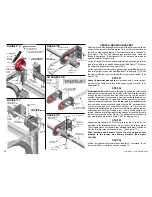
The following measurements are important to verify:
Lengths are the same on RA or RB Shields, up to the flag splice hole.
I
for metal doors and 4” (102) increments in wood
doors.
•Steel or Alum. Jambs:
Drill 5/16” (8) hole. Fasten with 3/8” x 1” self tapping screws.
•Block type Jambs
(Hollow, etc.)
:
Buy the correct fasteners from a local supplier.
Drill 3/8“ (10) holes for 2” (51) plastic
anchors.
f the door is less than standard height, be sure to check all
measurements. If measurements are not correct, cut off the bottom of
the vertical tracks and the RA or RB Shields the amount the door
furnished is less than the standard door height. Door height reductions
are in 3“ (76) increments
Standard Bottom Weather Seal on door should fit floors 1“ (25) out of
level. Optional 2 ½” (64) Bottom Weather Seal is available from the
factory for floors up to 2 ½” (64) out of level.
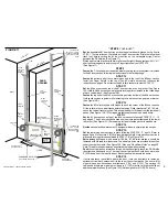
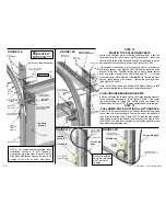
FASTEN RA or RB SHIELDS TO THE JAMBS
Make
sure the marks made on the left and right jambs during step 1 are
visible. The marks were made about 1¾“ (45) more than each door
section side width. These new marks are the outside of the RA or RB
Shields which total 3½” (89) more than door width. (See Figure 9)
Set
the RA or RB Shields on the same cardboard strips, placed on the
floor, behind the jambs, to level the door section in STEP 1.
Use
“C” clamps or nails to hold the RA or RB Shields in place until they
are fastened in a plumb position, in line with the marks. (See Figure 9)
Note:
“C” clamps are easy to use on any type jamb.
Drill
holes for fasteners at each bracket location. Make sure the fastener
holes are the same measurement up from the level cardboard strips
placed to level the door section in STEP 1. (See Figure 9)
•Wood Jambs:
Drill 1/8” (3) holes then fasten with 5/16” x 2” lag screws.
•Steel Jambs:
Drill 1/4” (6) hole. Fasten with 5/16” x 3/4” self tapping screws - or weld.
•Concrete, Brick or Stone type Jambs:
Push anchors in holes and fasten
with 5/16“x2” lag screws.
Measure
the width from RA or RB Shield to RA or RB Shield at the top
and at the bottom. Verify that each measurement is about 3½“ (89)
wider than the door width. Check to make sure all fasteners in RA or RB
Shields are tight and strong. (See Figure 9)
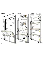
Fasten
the left vertical track to the left splice plate or splice bracket with
¼“ x ½” short neck carriage bolts and lock nuts. Finger tighten only until
STEP 15. (See Figure 10)
*
A
B
C
D
E
F
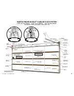
FIGURE 9
LEVEL
EV L
L
E
HEAD
ER
C I I
G
E L N
LEFT
JAMB
(8
O E T
DOO D
3-1/2“ 9)
M R
HAN
R WI TH
(
T IDE D
TO
OU SI E EDGE)
OU S
E GE
T
D
FLAG
SPLICE
PLATE OR
SPLICE
BRACKET
TRACK
BRACKETS
SPLICE HOLE
76“ (1930)
7’ (2130)
HIGH DOOR
RA SHIELD
LEFT
REVERSE
ANGLE OR
REVERSE
BRACKET
SHIELD
(RA OR RB
SHIELD)
FIGURE 10
SPLICE
PLATE OR
SPLICE
BRACKET
FLAG
REVERSE
ANGLE OR
REVERSE
BRACKET
SHIELD
(RA OR RB
SHIELD)
TRACK
BRACKETS
58“ UP
38“ UP
10“ UP
LEFT
VERTICAL
TRACK
1/4“X1/2
SHORT NECK
CARRIAGE BOLTS
1/4“
LOCK
NUTS
1/4“
LOCK
NUT
1/4“X1/2”
SHORT NECK
CARRIAGE
BOLT
5/16“X2”
LAG SCREW
CARDBOARD STRIPS
(SEE FIGURE 1 AND STEP 1)
5/16“x2”
LAG SCREW
DOOR
OPENING
NOTE: ADDITIONAL TRACK
BRACKETS CAN BE ADDED
FOR HIGH WIND LOADS
MARK
(SEE FIG.1
& STEP1)
PLUMB
(2130)
(2440)
(2740)
(3050)
(3660)
(4270)
(4880)
(5490)
STANDARD VERTICAL
TRACK LENGTHS
STANDARD DOOR
HEIGHTS
=
=
=
=
=
=
=
=
*
76“
88“
100“
112“
136“
160“
184“
208“
(1930)
(2240)
(2540)
(2850)
(3450)
(4060)
(4670)
(5280)
7'
8'
9'
10'
12'
14'
16'
18'
=
NOTE: Some models
provide Reverse Bracket
Shields (RB SHIELD) and
Splice Bracket (no Flag)
See Page 17 for
installation modifications.
COPYRIGHT © 2004 MARTIN DOOR


