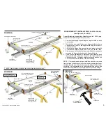
INSTALLATION INSTRUCTIONS FOR A MARTIN FINGER
SHIELD™ SECTIONAL GARAGE DOOR SYSTEM.
THESE INSTRUCTIONS ARE INTENDED FOR PROFESSIONAL
GARAGE DOOR INSTALLERS. READ THROUGH THE COMPLETE
INSTRUCTION MANUAL AND APPLICABLE SUPPLEMENTAL
INSTRUCTIONS ENCLOSED BEFORE BEGINNING.
STEP 1
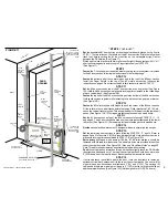
Study
the “Door Opening Information” measurements and supplement
B, page 19. Be aware of the following common obstructions: Closet,
fireplace, lighting, heat ducts, etc. The jambs and the header should form
a flush inside surface. Note: Martin sectional doors are manufactured
2“(51) over common USA door opening widths and ½” (13) over common
USA door opening heights. Example: A 16’ x 7’ (4880 x 2130) door is
manufactured 16’2” wide by 7’ ½” (4930 x 2150) high. The extra expense
for special door molding (doorstop) is not required. (See Figure 1 and 2)
Note:
For safety , strength and appearance all doors are furnished with
Martin Reverse Angle Shields. They fasten directly to the left and right
door jambs on most surface types. (See Step 8)
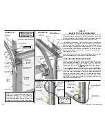
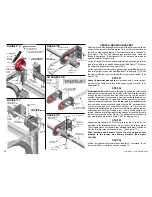
The door opening should be prepared as shown in Figure 1.
For strongest and best appearance, old framing should be removed (See
Figure 2) and the old door opening finished with all surfaces flush as
shown in Figure 1.
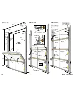
Place
two cardboard strips on each side of the door opening.
Center one
of the door sections behind the door opening, setting it on the two
cardboard strips. Add cardboard strips to one side, if necessary, to make
the door section level. Strips are cut from cardboard shipping angle. Mark
both jambs 1 ¾” (45) wider than each side of the level door section. The
two marks are important to correctly begin fastening the Reverse Angle
Shields to the door jambs in STEP 8. (See Figures 1 and 9)
Note:
Most headers are level (Most floors are not level).
DOOR
OPENING
INFORMATION
Measurements shown are with 4“ (102) cable drums and 2” (51) tracks
----See supplement B page 19, for other clearances and modifications----
FIGURE 1
FIGURE 2
FLOOR
FLOOR
CEILING
HEADER
WALL
WALL
HEIGHT SHOULD BE
AT LEAST .5“ (13)
LESS THAN DOOR
HEIGHT (SEE STEP 1)
MINIMUM HEIGHT
IS 12“ (310) MORE
THAN DOOR HEIGHT
(SEE STEP 2)
DOOR
OPENING
THE VIEW IS FROM THE
INSIDE LOOKING OUT
MINIMUM CLEARANCE IS
12“ (310) MORE THAN
DOOR HEIGHT. ADD 3“
(76) FOR DOOR OPENER
MINIMUM WIDTH
IS 3.5“ (89) MORE
THAN DOOR
WIDTH
MINIMUM WIDTH
IS 3.5“ (89) MORE
THAN DOOR
WIDTH
3
HEADER
LEFT
JAMB
RIGHT
JAMB
CENTER
SPRING PAD
FRAMING EXAMPLE FOR
WOOD JAMBS AND HEADER
2 X 4 OR 2 X 6 OR 2 X 8
(51X102) (51X152) (51X203)
LEFT
JAMB
RIGHT
JAMB
DOOR OPENING WIDTH SHOULD BE AT
LEAST 2“ (51) LESS THAN DOOR WIDTH
(SEE STEP 1)
LEVEL
DOOR SECTION
COPYRIGHT © 2004 MARTIN DOOR
MARK
1 ¾” (45)
MARK
1 ¾” (45)
TWO CARDBOARD STRIPS
TWO CARDBOARD STRIPS
*
*
(ADD CARDBOARD STRIPS TO ONE SIDE ONLY TO LEVEL DOOR SECTION)
CARDBOARD STRIPS ARE CUT FROM CARDBOARD SHIPPING ANGLE.
*
OLD FRAMING TECHNOLOGY
The required clearance above a door furnished with 4“ (102) diameter
cable drums is 12” (305) when using 2” (51) track or 17” (432) when using
the optional 3” (76) track. See supplement “B”, page 19 for clearance and
modifications information if the required clearance needs to be
changed. More clearance is required for bigger diameter cable drums.
See “Wood Door Notes” 3 and 4 on page 22.
Martin Low Clearance Track Kits are only available for 2“ (51)Track and
includes safer inside lift cables.
STEP 2
INSTALLATION OF THIS SECTIONAL DOOR CAN BE
DANGEROUS. CALL A TRAINED MARTIN DOOR DEALER
NOTE:
Builders, Architects, and Design
Engineers must consider forces
transmitted by the door to the building
structure as a result of wind load and/or
door weight. This consideration includes
the door opening structure and the
supporting structures for the door track
assembly.
Contact Martin Door Mfg. for additional
or specific load requirements.


