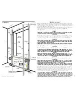
HOW TO INSTALL LOW CLEARANCE TRACKS IN 3/4“ (19) LESS CLEARANCE.
This is not recommended but may be necessary.
1. Cut off bottom of RA or RB shields and vertical tracks 4-1/4“ (108) --not 3-3/4” (95). See page 20.
2. Do not add the three additional cardboard strips under the reverse angle shields and the door. See page 20.
3. The top of the vertical tracks should be about 12-1/2“ (318) from the top of the closed door-- not 11-3/4” (298). See page 20.
4. Fasten the front of the low clearance tracks to the second hole of the horizontal track angles -- not the third hole. See page 20. Caution! Leave space for the lift cables.
5. The top section may need to be adjusted back from the header up to 1/2“ (13) to clear the spring anchor brackets, as the door opens and closes.
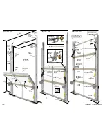
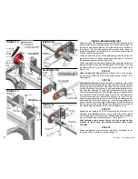
FIGURE C6
LOW
CLEARANCE
TRACK
1“ (25) PUNCHED ANGLE BRACKET
HORIZONTAL
TRACK
HORIZONTAL
TRACK ANGLE
¼“X½” SHORT NECK
CARRIAGE BOLT AND
¼“ LOCK NUT
1“ (25) PUNCHED
ANGLE BRACKET
SIDE VIEW
END VIEW
HORIZONTAL
TRACK ANGLE
LOW CLEARANCE TRACK CHART
Clearance above top of closed door for 4“ (102) cable drums.
Top of LC Tracks above top of closed door.
Clearance above top of closed door for door trajectory.
Door open, at rest, under top of closed door line.
Door open, at maximum, under top of closed door line.
Top of Vertical Tracks to top of closed door.
This is the INSTALLATION MEASUREMENT.
Clearance above top of closed door for 5 ¼“ (133) cable drums.
8“ (205)
3 3/4“ (95)
5“ (127)
-5“ (-127)
0“ (0)
11 3/4“ (298)
Torsion
at Front
10“ (254)
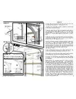
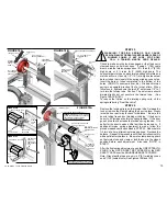
FIGURE C5
LOW CLEARANCE TRACK
HORIZONTAL TRACK
TOP OF DOOR
TOP OF VERTICAL TRACK
ABOUT
11-3/4“
(298)
SPRING ANCHOR
BRACKET
SPLICE
PLATE OR
SPLICE
BRACKET
LOCK-ON SIDE
BEARING BRACKET
TORSION
TUBE
BLACK
CABLE DRUM
LOCK-ON SIDE
BEARING BRACKET
FLAG
TOP ROLLER BRACKET
ROLLER AND
ROLLER SHIELD
LOW PROFILE HINGE
TEMPORARILY
REMOVE STRUT
IF MORE SPACE
IS NEEDED TO
WIND SPRINGS
“L” STRUT
HORIZONTAL
TRACK
ANGLE
REVERSE
ANGLE
SHIELD OR
REVERSE
BRACKET
SHIELD
VERTICAL
TRACK
TOP DOOR SECTION
LOW CLEARANCE TRACK
PUNCHED ANGLE
(OPTIONAL)
21
COPYRIGHT © 2004 MARTIN DOOR
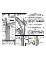
STEP 18
Follow the first paragraph of the regular instruction manual, except turn the top roller brackets over
and reverse the roller tubes. Adjust the roller tubes close to the door section. Fasten each top roller
bracket in the holes provided in the stiles. (See Figures C3,C4) NOTE: For doors over 8’(2440)
high top roller brackets have a brace. Fasten top roller brackets to the top outside holes. The
matching top two outside holes are in the stiles, under the
skin. The 1/4 X 1” Thread
Forming Screws will penetrate the
skin while turning. The strut if provided, may install 2”
(51) lower. On four section high doors, remove the roller shields from the top rollers..
ADJUSTMENTS:
The roller tubes can be adjusted back slightly to keep the top section against
the header. The vertical slot at the front of the Low Clearance track is provided so the track can
move up and down slightly to also adjust the top section against the header.
STRUT:
If the top section has
strut, the strut must be turned over and fastened over the top
roller brackets or fastened to the stiles as close to the top of the door as possible. (See Figure
C3,C4)
STEPS 19 TO 29
Follow the regular instruction manual. (Step 26 note: Temporarily remove
strut if more space is needed to wind the spring(s).)
metal
metal
an “L”


