Marshall Electronics V-MD151 Operating Instructions Manual Download Page 9

20

Use this feature to choose between controlling the Contrast of the image or the intensity of the panel’s Backlight with the
CONTRAST button on your monitor.

Note:

While the Contrast control moves up and down at intervals of 1, the Backlight

control will move up and down at intervals of 2, from 0-100.

Load Setup

Select this menu item to reset all adjustments and menu settings to the factory default configuration or to one of the user
configured presets.

Save Setup

Select this menu item to save a current setup into one of 6 available user presets.

Power On Preset

Select this menu item to reset all adjustments and menu settings to the factory default configuration whenever the unit is
powered down.

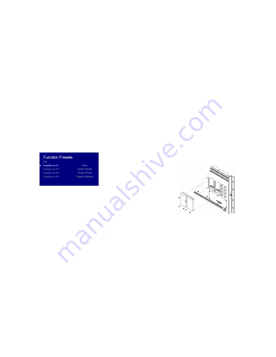
FUNCTION PRESETS SUBMENU

Function Presets

Allows user to assign menu items to the front panel function buttons:

F1, F2, F3 and F4.

The following options are available

for each button:

Ratio

Check Field

Mosquito Filter

False Colors

Freeze Input

Aspect Markers

Center Marker

Marker Enable

Underscan

H/V Delay

Pixel-to-Pixel

IMD & TALLY CONFIGURATION

9

Input Module Installation

1. Remove Power From Unit

Modules are cold-swappable only. Damage will occur if modules are inserted or removed while unit is

powered.

2. Remove Blank Module Cover

Using Philips screwdriver, remove the 4-40x1/8” screws. There are a total of three screws, save them for later
use.

Remove blank cover

3. Insert Optional Module

Decide which slot you intend to install module (Slot 1 or Slot 2)

Carefully align the module with the chosen slot. The raised rails will fit inside the module

Align the Module so that the three (3) mounting holes all line up with the threaded holes of the slot.

The connectors on both the module and the main-board slot should now be in alignment.

Carefully PRESS the module into the slot. Module will seat flush with the rear of the unit.

Replace the three (3) screws removed in Step 2.

*NOTE* Use ONLY 4-40x1/8” screws provided. Any screw longer than 1/8” will damage the main unit.

Summary of Contents for V-MD151

Page 1: ...ronics Inc 1910 East Maple Ave El Segundo CA 90245 Tel 800 800 6608 310 333 0606 Fax 310 333 0688 www LCDRacks com sales lcdracks com Model No V MD151 Rack Mountable High Definition LCD Monitor Operat...

Page 2: ...ts original container for a period of one year from the purchase date This warranty is extended to the first consumer only and proof of purchase is necessary to honor the warranty If there is no proof...

Page 3: ...26 Page Intentionally Left Blank 3 Page Intentionally Left Blank...

Page 4: ...8 Input Module Installation 9 MAIN MENU AND NAVIGATION 11 VIDEO CONFIGURATION SUBMENU 11 MARKER CONFIGURATION SUBMENU 14 FILTER CONFIGURATION SUBMENU 17 SYSTEM CONFIGURATION SUBMENU 19 FUNCTION PRESET...

Page 5: ...Dimensions section for more information A VESA standard 75mm hole pattern also allows custom mounting installations Alternately the V MD151 can be used in a desktop configuration with optional stand...

Page 6: ...een are available above the screen 23 Specifications PANEL Screen Size 15 6 Diagonal Display Area h x v 344 16 x 193 59 mm Pixels 1920 x RGB x 1080 Viewing Angle h x v 160 x 145 Brightness 600 cd m2 C...

Page 7: ...other than the included power supply damage may result Please use the pin out diagram in the Specifications section Tally Input Connector The LED tally can be activated via the HD 15 connector by conn...

Page 8: ...x 768 60 75 85 1280 x 1024 60 75 1600 x 1200 60 CVT Timing 1920 x 1200 60 CVT Timing 21 Text Enable Use the Text Enable function to turn the MD Text feature ON This will cause the Text String to appe...

Page 9: ...ton Ratio Check Field Mosquito Filter False Colors Freeze Input Aspect Markers Center Marker Marker Enable Underscan H V Delay Pixel to Pixel IMD TALLY CONFIGURATION 9 Input Module Installation 1 Remo...

Page 10: ...e of the display Input Format OSD Use this option to enable on screen display of input format status in the upper left corner of the screen Curtain Color Use this option to change the curtain color on...

Page 11: ...front panel of the monitor Step through menu items using the and buttons Choose a submenu or select a menu item by pressing SELECT Return to the previous menu by pressing MENU Exit the main menu by p...

Page 12: ...s shown below The buttons affect whichever row of controls gain or bias is currently selected Check Field Use the check field modes for monitor calibration or to analyze individual color components of...

Page 13: ...ray bars at the lower right corner of the screen Adjust the Brightness button until there is no visible difference between the super black and black bars but the gray bar is still visible 5 Adjust the...

Page 14: ...u to select various video settings such as monochrome mode or blue only mode Marker Enable Marker Configuration Submenu 15 Use this setting to enable or disable all on screen markers This setting affe...

Reviews: